Close
0%
0%

PiDP-11 I/O Expander

16-Bit TTL Compatible I/O Expander for the PiDP-11 and Raspberry Pi

Similar projects worth following
Starting from
$29.00
sstallion has 76 orders / 0reviews
Ships from United States of America
The PiDP-11 I/O Expander adds 16 GPIO pins with interrupt capability to Oscarv's excellent PiDP-11 project. These pins can be used to interface with components located in the built-in prototyping area or with external hardware. If 16 pins aren't enough, multiple boards can be chained together to add up to 128 GPIO pins to a single system.

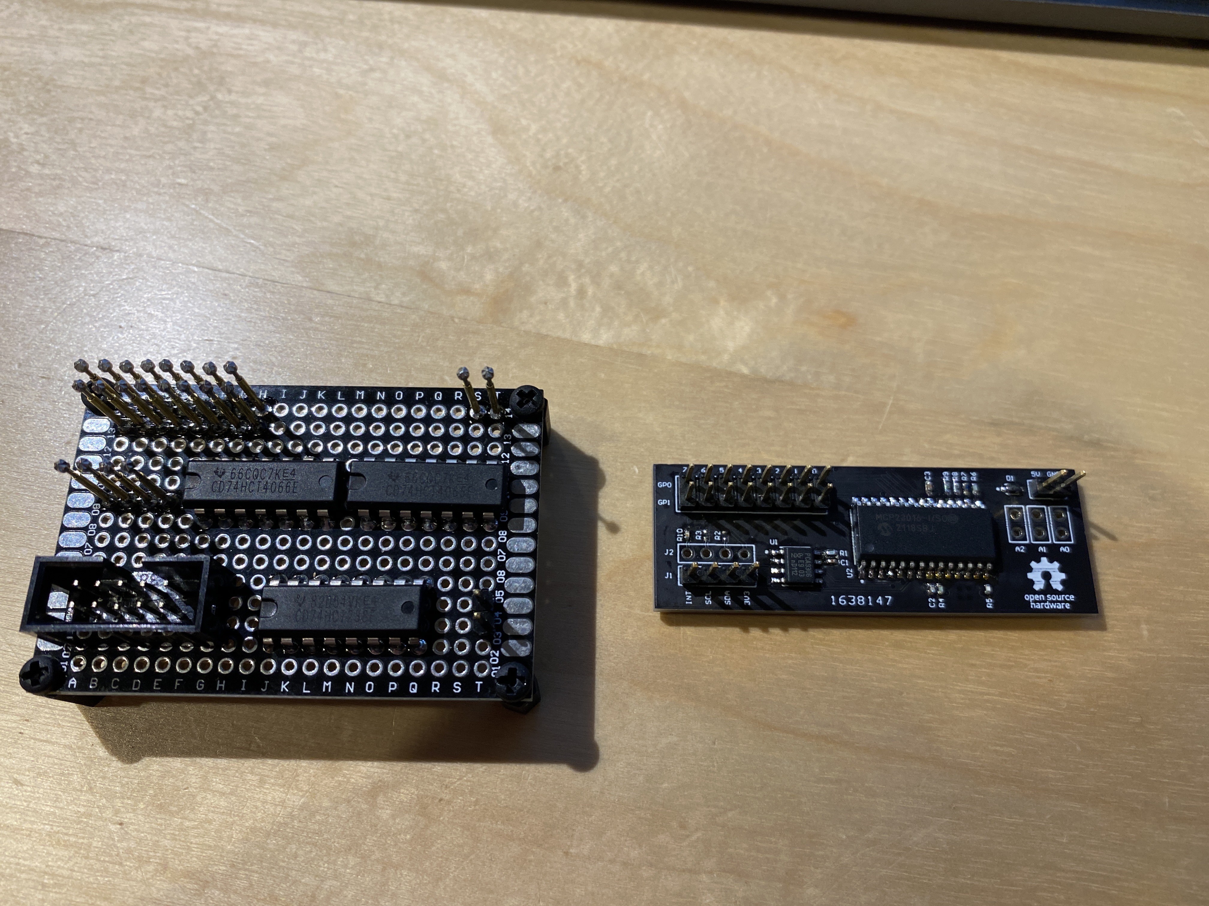
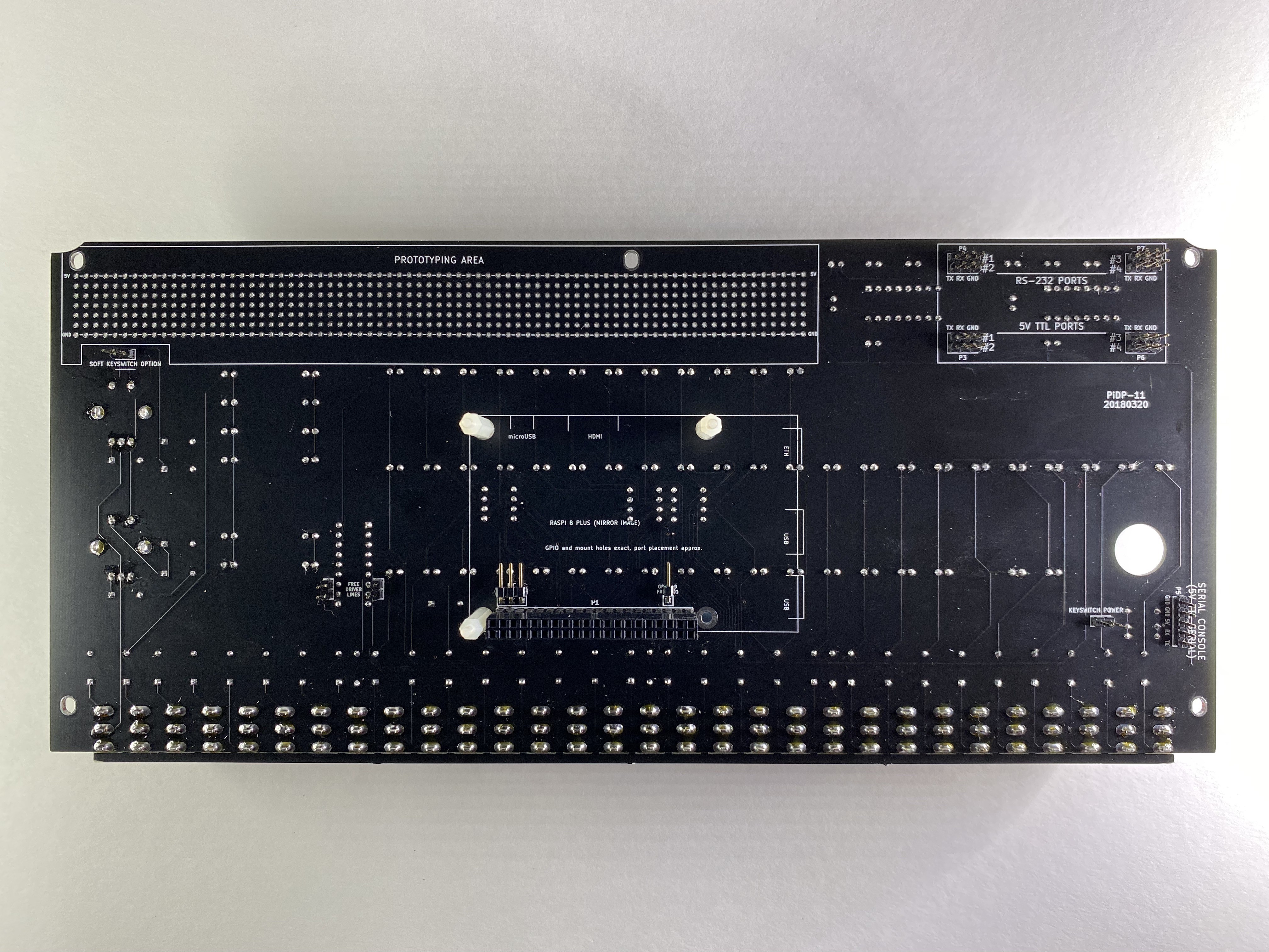
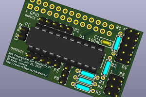
The heart of the I/O Expander is a Microchip MCP23016, which is similar in function to the popular MCP23017 with the added benefit of TTL compatibility to support both 3V3 and 5V logic levels. The I/O Expander provides GPIO access to 16 pins over I2C (up to 400kHz), which can be independently configured and controlled by software. Interrupts are fully supported and routed to GPIO 19 on the Raspberry Pi.

Up to 8 I/O Expander boards may be connected in series to increase the total number of GPIO pins to 128. Rework may be needed to support multiple boards (eg. adjusting pull-up resistor values) depending on installation method and overall bus capacitance. Additional pin headers must be also be fitted and shunted to configure I2C addresses to avoid bus conflicts.

For more details, see the latest release on GitHub.

Adobe Portable Document Format - 230.07 kB - 09/02/2021 at 00:47

Preview
Download

Adobe Portable Document Format - 472.66 kB - 09/02/2021 at 00:47

Preview
Download

sheet - 23.29 kB - 09/02/2021 at 00:47

Download

Adobe Portable Document Format - 131.30 kB - 09/02/2021 at 00:47

Preview
Download

Adobe Portable Document Format - 88.41 kB - 09/02/2021 at 00:47

Preview
Download

  • 1 × PiDP-11
  • 1 × I/O Expander PCB Assembled PCB with SMT components
  • 6 × Jumper Wires Jumper wires to connect 5V/GND and I2C to the PiDP-11
  • 4 × Pin Headers Through-hole pin headers for 5V/GND, I2C, I/O, and the PiDP-11
  • 1 × Double-Sided Tape VHB 4910 to mount the I/O Expander PCB to the PiDP-11

  • Back in Stock!

    Steven Stallion01/27/2023 at 19:55 0 comments

    Assembled boards are back in stock and available for purchase from Tindie: https://www.tindie.com/products/sstallion/pidp-11-io-expander-kit/

  • Code Complete

    Steven Stallion10/16/2021 at 03:36 0 comments

    I am happy to report the software for the PiDP-11 I/O Expander is finally complete! I've posted installation instructions, a brief theory of operation, and usage on GitHub along with a new release tarball which contains an updated SIMH.

    I have to admit, It's been quite satisfying to finally program external hardware using the switch register. This should hopefully be everything that is needed for folks to begin writing device drivers in their OS of choice.

  • Back in Stock!

    Steven Stallion10/07/2021 at 22:28 0 comments

    Assembled boards are (finally) back in stock and available for purchase from Tindie: https://www.tindie.com/products/sstallion/pidp-11-io-expander-kit/

  • Tindie Store

    Steven Stallion09/02/2021 at 01:20 0 comments

    If you'd like to purchase an I/O Expander kit for your PiDP-11, assembled boards are available for purchase from Tindie: https://www.tindie.com/products/sstallion/pidp-11-io-expander-kit/

    This kit contains everything needed to expand the I/O capabilities of your PiDP-11:

    • I/O Expander PCB (Assembled & Tested)
    • Jumper Wires
    • Pin Headers
    • Double-Sided Tape

  • Automation Saves Your Sanity

    Steven Stallion09/01/2021 at 17:36 0 comments

    While gathering photos for the previous post, I found a video demoing test fixture operation. Developing the test fixture and corresponding functional tests were a lot of fun. In past projects I've relied on a combination of bench validation and spot checks. I've never had a board returned due to defect, but I worried nonetheless. Having this part of the process fully automated not only saved a lot of time, it also saved my sanity™️.

  • Behind The Scenes

    Steven Stallion09/01/2021 at 16:49 0 comments

    I have a habit of taking a ridiculous number of photos when working on a project. I especially enjoy looking at the various things I thought were important at the time - every now and then a photo stands out.

    Enjoy 🎉

    This was one of the earliest photos I could find. On the right is the first prototype I hand soldered to validate the design. On the left is a prototype test fixture that used a bit of discrete logic and a Total Phase Aardvark for functional testing. I was hoping to get away with something simple, however the insertion force was just too great to be done by hand and the idea was scrapped before populating the rest of the board.

    I spent a bit of time researching cheaper alternatives to press fit jigs, especially since the naive approach of using pogo pins mounted to perfboard failed miserably. I stumbled across Merifix and purchased a fixture kit (the drilling service is highly recommended). I kept the same interface, but switched to a larger perfboard to better support terminal blocks to connect test probes.

    Top side of the test fixture with locating and test probes installed. If you look closely, the prototype PCB lying on the drill plate lacks tooling holes. Fortunately, I was able to remove the locating probes to continue working on the functional test suite while I waited for the next board revision to come in.

    Production panels with stencil. Only minor adjustments were needed for this revision; silkscreen artifacts in the prototype were cleaned up and tooling holes were added for test fixture placement.

    A shot of my bench after finishing assembly for the first run of boards. It's a mess, but it's home.

    I think it was at this point I realized how difficult it is to take good photos using a white background. Lighting will forever be my bane.

    Finally, a lazy morning reviewing an early draft of the fabrication drawing.

  • Project Retrospective

    Steven Stallion09/01/2021 at 14:33 0 comments

    I first encountered Oscarv's PiDP-8/I project while browsing Hackaday back in 2017. Like many a maker, I dutifully bookmarked the project in my RSS reader (where it still sits today) and turned my attention toward other projects with the intention of swinging around when I had more time. History repeated itself when the PiDP-11 was released and later featured on Hacker News and I knew this would be the year to finally take on building a PiDP kit for myself.

    While building the kit, I noticed that while there was a generous prototyping area on the PiDP-11 PCB, there were limited options for integrating it with the Raspberry Pi. Fortunately, Oscar's design exposed the Raspberry Pi's I2C pins in addition to a single unused GPIO pin, which was just enough to squeeze in an I2C I/O Expander. I struck up a conversation with Oscar about enhancing the PiDP-11 with an expansion board and he encouraged me to reach out to the wonderful PiDP-11 community on Google Groups to gauge interest. An enthusiastic response followed and I began work on the design in mid-June.

    The design revolved around choosing a suitable I2C I/O expander. I settled on the MCP23016 over the MCP23017/18 as it was the last model that supported TTL logic levels, which would allow mixing 3V3 and 5V logic (period accurate for the PDP-11/70). The interrupt logic was also simpler and limited to a single open drain output, which wouldn't require a buffer to integrate with the Raspberry Pi. Once the I/O expander was selected, a bi-directional I2C level shifter was added to translate signals to/from the Raspberry Pi.

    One of the unexpected pleasures of working on such a simple design was being able to focus on the manufacturing and packaging processes. This was the first project I've worked on where I needed to manufacture more than a dozen boards at a time. To keep things simple, I did all of the SMT assembly myself with a benchtop reflow oven and manual paste application using a stencil. A test fixture was needed to validate assembly before packaging PCBs since through hole components would be packaged separately. This was also a chance to dip my toe in having custom cable assemblies manufactured in larger quantities than I can do myself.

    Overall, I'm very pleased with the results, and I hope you will be too! This project was a great reminder that even smaller efforts can have something to teach - it's just a matter of focusing on the right things.

  • Clock Stretching (Sigh)

    Steven Stallion08/31/2021 at 02:35 0 comments

    Unfortunately it looks like the MCP23016 is no exception when it comes to clock stretching on the Raspberry Pi. For those that may not be familiar, clock stretching is a method for throttling an I2C master that is communicating too quickly by having the slave temporarily hold SCL low. Under normal circumstances, clock stretching goes unnoticed unless examined with a scope or logic analyzer, however the SoCs that power the Raspberry Pi have a long-standing bug that breaks this behavior.

    The good news is there is a simple workaround to address the issue, though it requires reducing the bit rate for the entire bus to eliminate the need for clock stretching. The bad news is this is not enabled by default.

    To reduce the bit rate to 10kHz, update the following line in /boot/config.txt and reboot:

    dtparam=i2c_arm=on,i2c_arm_baudrate=10000

     After rebooting, you can verify proper communication by issuing:

    $ i2cdump -y -r 0x00-0x0b 1 0x20 b
         0  1  2  3  4  5  6  7  8  9  a  b  c  d  e  f    0123456789abcdef
    00: 00 00 00 10 00 00 ff ff 01 00 00 00                ...?....?...
    

    It's a shame this is still an issue on modern Raspberry Pis. The Raspberry Pi 4 added support for clock stretching via software I2C, but it looks like this limitation will continue to persist in hardware for the foreseeable future.

View all 8 project logs

  • 1
    Prepare the PiDP-11

    If you have already built your PiDP-11 kit, you will need to remove the PCB from the case such that you have access to both sides for soldering. The Raspberry Pi should be removed from the GPIO connector.

    If you are building your PiDP-11 kit, follow the Official Instructions to the point you would solder the GPIO connector to the PCB. This is not mandatory, but it does make the following steps a little easier.

  • 2
    Solder PiDP-11 Headers

    Carefully separate a single pin from the 4 position right-angle pin header using a sharp pair of cross cutters. The 3 position header should be soldered to the I2C pads, and the single position header should be soldered to the GPIO 19 FREE I/O pad above the GPIO connector on the back of the PiDP-11 PCB as shown below:

  • 3
    Solder I/O Expander Headers

    Solder the 2, 4, and 16 position vertical pin headers to the 5V/GND, I2C (J1), and I/O pads, respectively. A sacrificial breadboard can be used to align pins and ease soldering.

View all 8 instructions

Enjoy this project?

Share

Discussions

Justin Davis wrote 09/02/2021 at 14:00 point

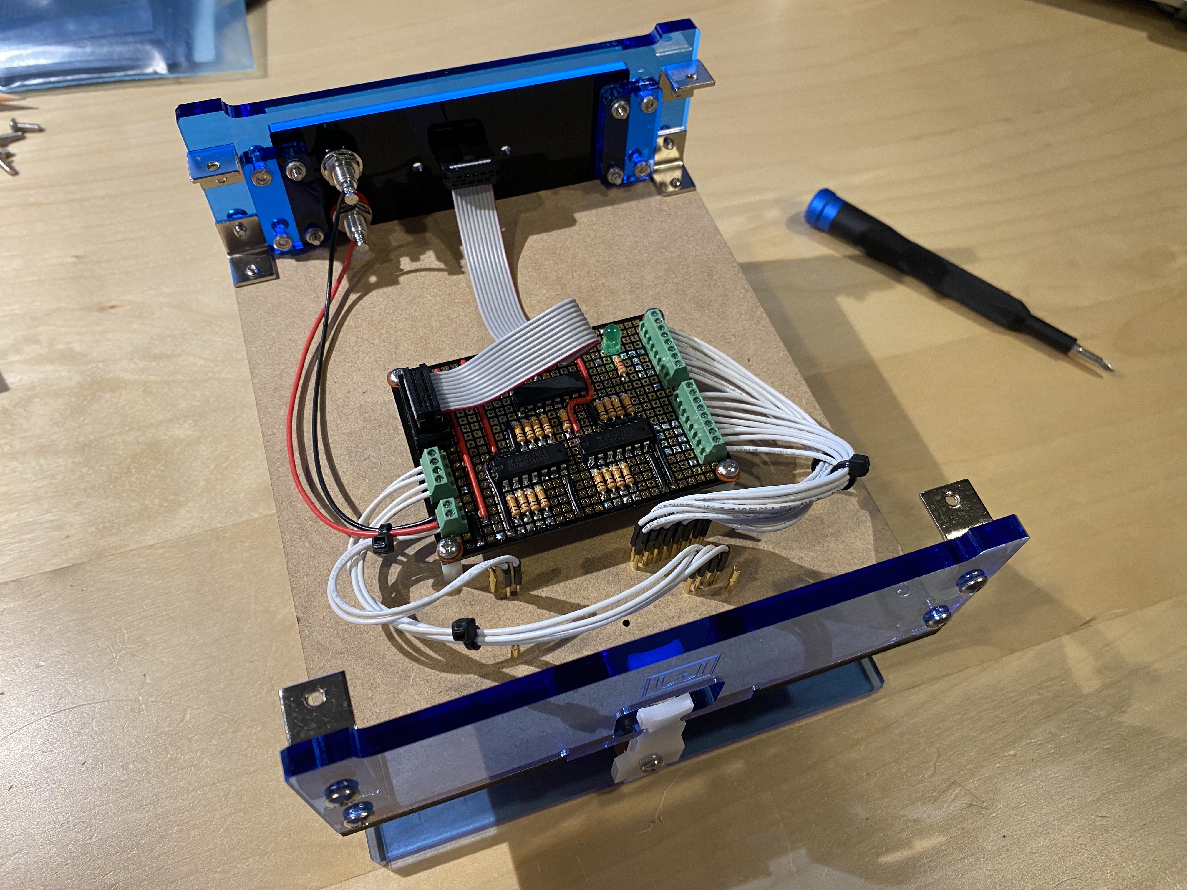
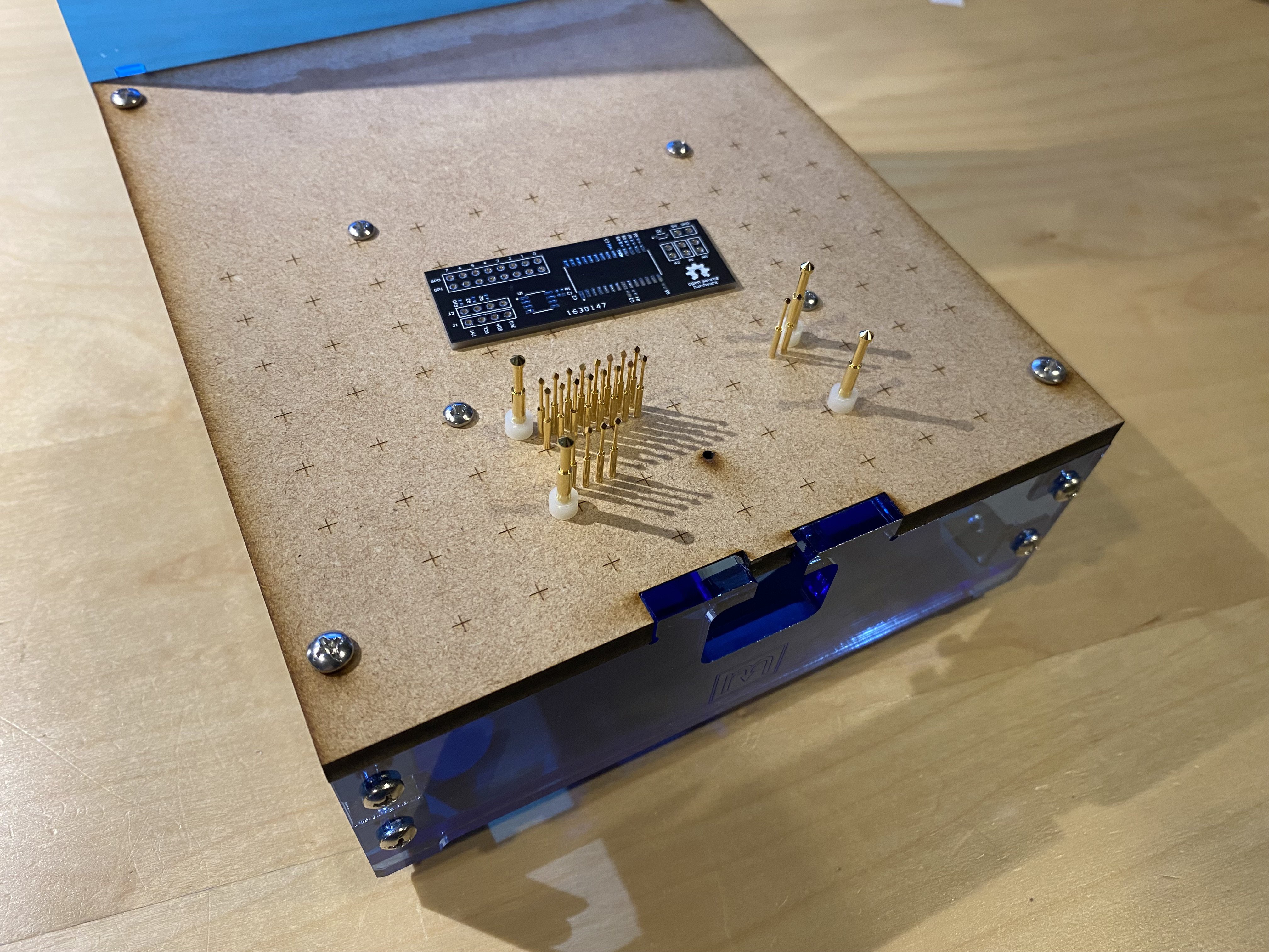
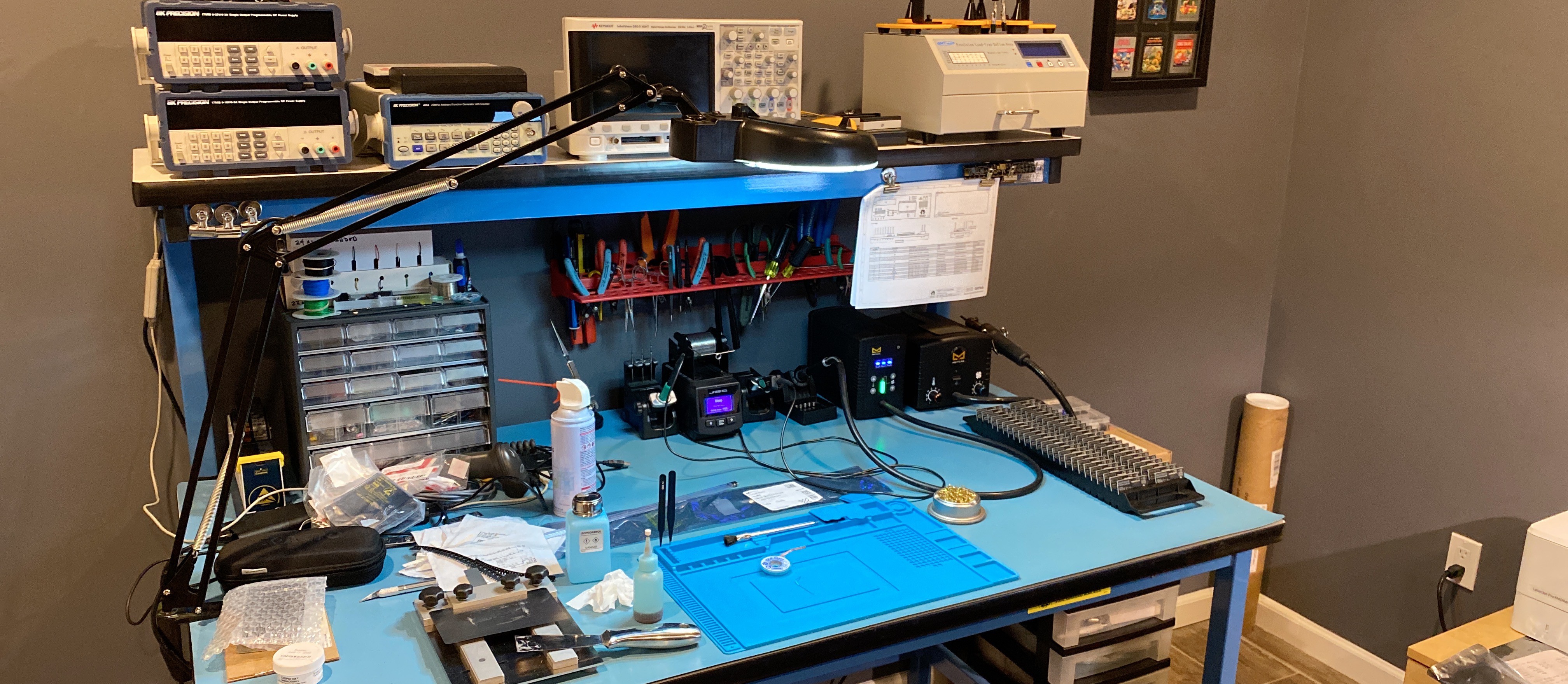
This is a great example of how to do test fixturing at home.  I think by far more than what most people would do at home, and approaching what is really done in a professional manufacturing facility.

  Are you sure? yes | no

Steven Stallion wrote 09/02/2021 at 16:21 point

Thanks! There's definitely an art to small-scale DFT. The Merifix fixture seemed to be a good compromise between a fully custom press fit jig and the cheap(er) bakelite alternatives on eBay. The construction is surprisingly solid, but probably won't hold up for medium-to-large production runs.

  Are you sure? yes | no

Similar Projects

Does this project spark your interest?

Become a member to follow this project and never miss any updates