 Tharindu Suraj Chathuranga
Introduction
Drone-based STEM education is one of the trending topics in the modern world but is limited to several countries and several communities due to the knowledge barriers and higher prices of the STEM drone platforms. Following are some of the key areas that students can learn with STEM drones.
- Basics of building.
- Experimenting with basic movements of flights.
- The physics of flight.
- Programming.
- Real-world problem-solving.
Currently available STEM drone platforms can be divided into 2 main groups.
- Drones with high level controlling
- Drones with low-level access
The drone which provides high level controlling is suitable for beginners who are not familiar with coding, physics and complex mathematical models. These drones are fairly cheap and can be programmed using block programming like Scratch. Students can learn basic movements of flight and real-world problem solving with these drones since they don't have to worry about flight stabilization, sensor inputs, and other complex mathematical models. The problem with these drone platforms is they do not provide access to its' internal parameters such as IMU measurements, PID outputs, etc. This limits the learning process up to a certain level and students need to buy another platform with low level access to continue the learning.
Usually drones which provide low-level access are expensive. This makes these drones affordable to a limited crowd. Further, most of these drones consist of highly complex algorithms so that students do not have an intermediate option when transiting from a beginner-level platform.
The LollyDrone project is started to solve the above problems in both beginner and advanced learning systems. The target is to implement both high- level commands for beginners and provide low-level but simple algorithms for intermediate students. The inspiration for this project was came from the XFly 1.0 Programmable drone by QubeBots.
The key advantages of the LollyDrone are,
- Build cost is under 20USD.
- Simple firmware implementation avoiding complex mathematical models
- Uses Arduino IDE for programming
- WiFi interface allows both mobile phones and laptops for communication
The number of components is limited in the design which makes the assembling process done within 10 minutes. All the electronics except motors and the battery are combined into a single PCB board. The frame can be 3D printed so that students do not need to spend on buying extra frames. Following are the key components of the drone.
- 3D printed frame
- 1S Lipo battery
- 716 coreless motors
- Custom made PCB
With all these components, the total weight is around 42g with a 280mAh battery which gives a flight time of around 7 minutes.
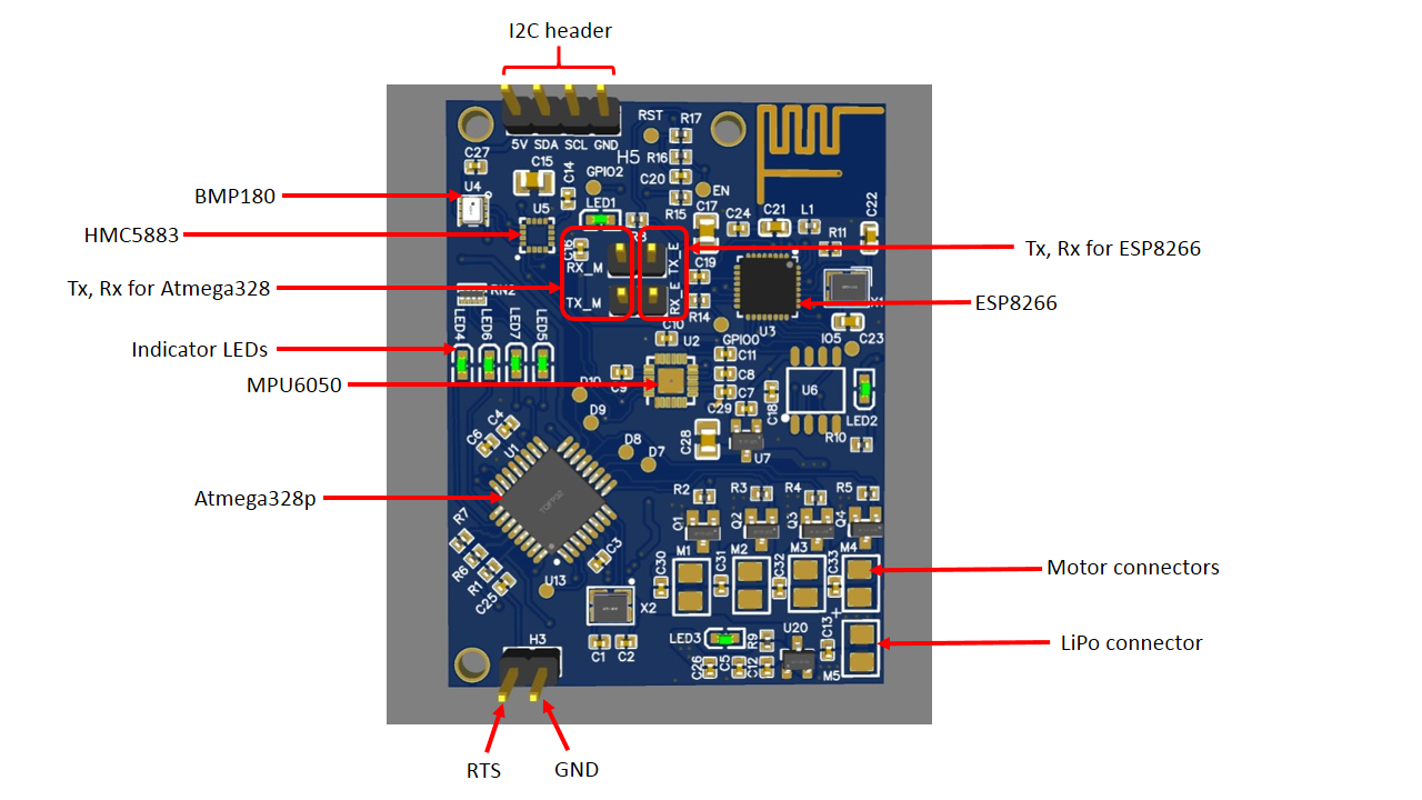
PCB
--------
The PCB is designed using EasyEDA and the size is 40mm X 53mm. The Atmega328 is dedicated to run the control system and ESP8266 handles the communication part. Coreless motors are directly driven by 4 MOSFETs.
Gerber files, BoM and Pick n Place files are attached under the files section.
The board can be programmed with the Arduino IDE through an FTDI converter. The Vcc, Gnd, Tx, Rx and RTS pins on the board should be connected to the respective pins of the FTDI converter.
Firmware
Flight Controller
The stabilization loop consists of the following processes.
- Read IMU
- Apply Complementary filter and calculate roll and pitch.
- Calculate corrections from PID.
- Calculate thrust for each motor and set the PWM.
The gyro and the accelerometer have been configured with 500dps and 8g ranges respectively. The I2C clock speed is changed to 400kHz to keep the communication time at a minimum level. The internal low pass filter of the accelerometer is configured to 184Hz to filter out unwanted vibration noise. The complementary filter is used to fuse the roll and pitch values calculated with the gyroscope and the accelerometer. A honorary mention about the engineering team of the SRQ Robotics for educating me about these topics.
A calibration process is included in the initialization of the firmware to calculate the gyro bias and initial roll and pitch angles. The drone needs to be placed on a flat and firm surface to facilitate this process.
The control loop runs at 250Hz. To keep the constant loop rate, a simple delay function is used inside the main loop.
while (micros() - loop_timer < 3080){}

if (micros() - loop_timer > 4050){
    motor_stop();
    while(1){}
}
The following function is used to combine PID outputs and calculate relevant PWM values for each motor. All the PWM values are saturated at 255 to facilitate the analogWrite() function in Arduino.
M1speed = base_thrust - pid_output_pitch + pid_output_roll - pid_output_yaw; //Calculate the pulse for M1 (front-right - CCW).
M2speed = base_thrust + pid_output_pitch + pid_output_roll + pid_output_yaw; //Calculate the pulse for M2 (rear-right - CW).
M3speed = base_thrust + pid_output_pitch - pid_output_roll - pid_output_yaw; //Calculate the pulse for M3 (rear-left - CCW).
M4speed = base_thrust - pid_output_pitch - pid_output_roll + pid_output_yaw; //Calculate the pulse for M4 (front-left - CW).
Testing
The following video shows how the drone performs after adding the thrust mapping function. The PID parameters can be tuned further to make the drone more stable.
Future works
- Integrate magnetometer readings with the control loop.
- Implement altitude hold function with the pressure sensor.
- Implement a mobile app based controller to fly the drone.
- Modify the PCB with pluggable motor connectors.