 Guillermo Perez Guillen
A video summarizing the journey of this project:
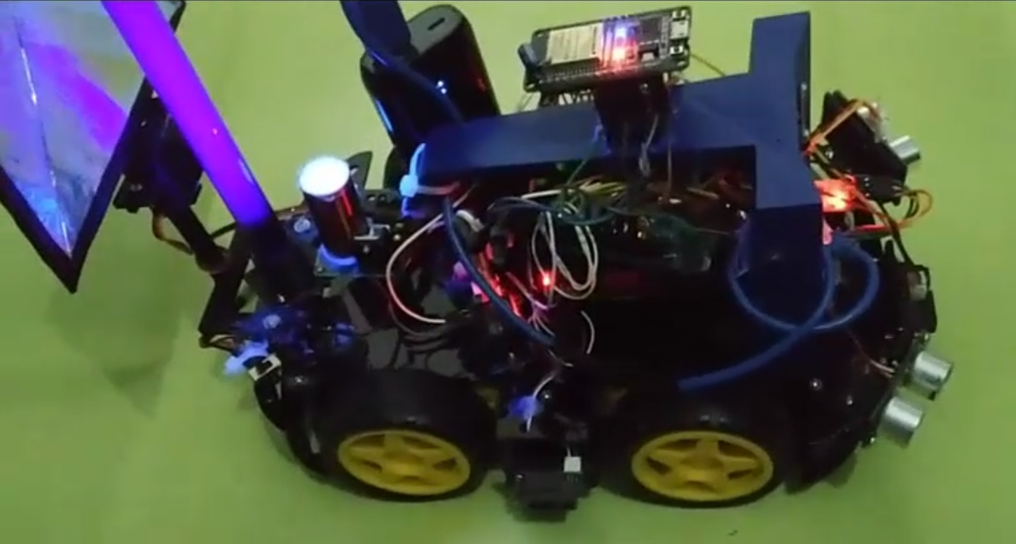
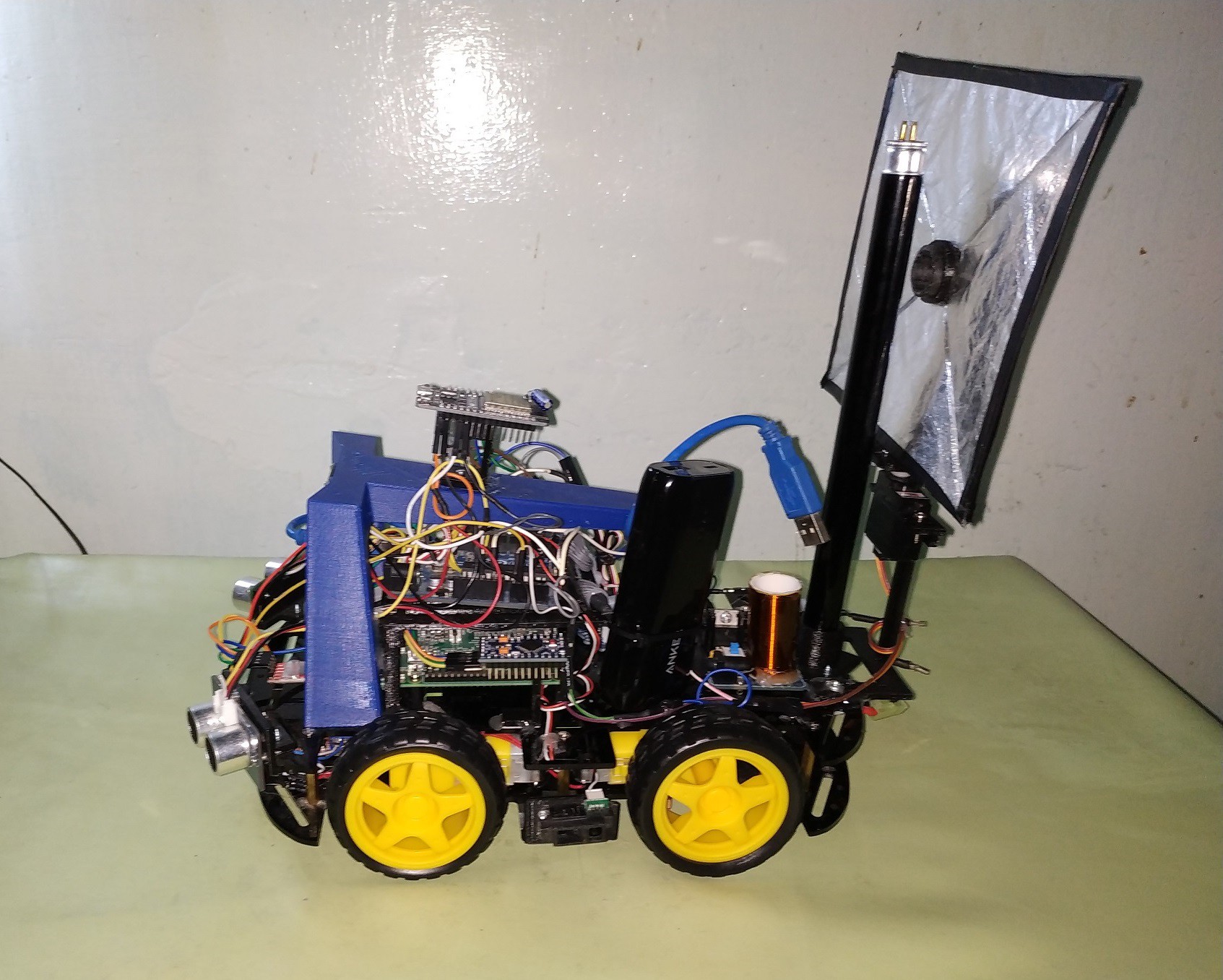
In Motion Version, specific goals:
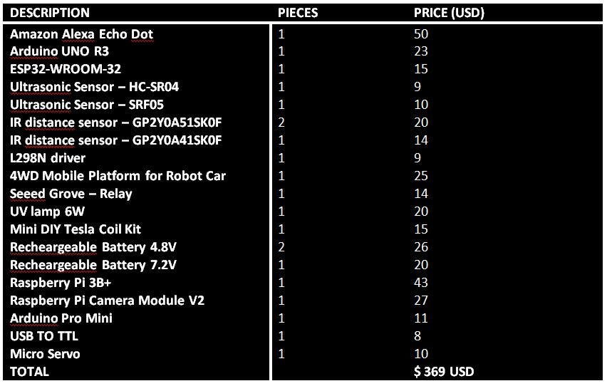
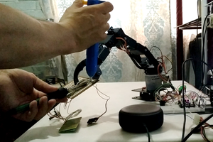
- 3D printing of the list of parts that will be used to assemble the Autonomous Robot;
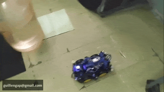
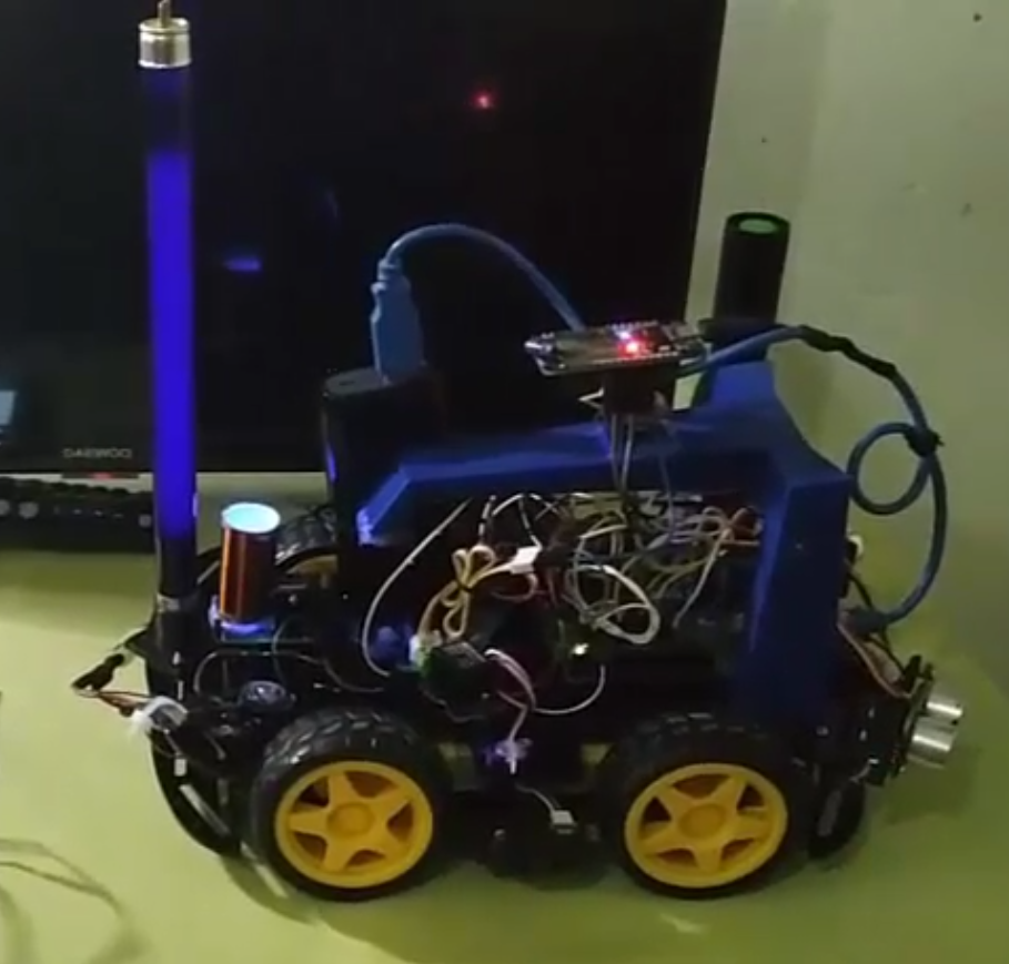
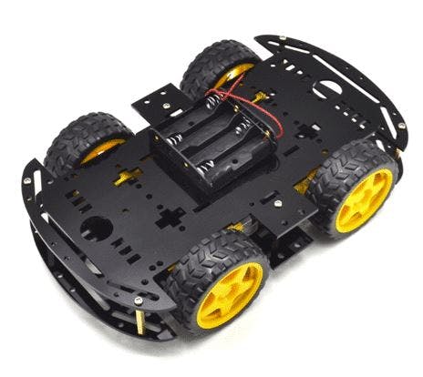
- Mounting the Chassis: "4WD Robot Car";
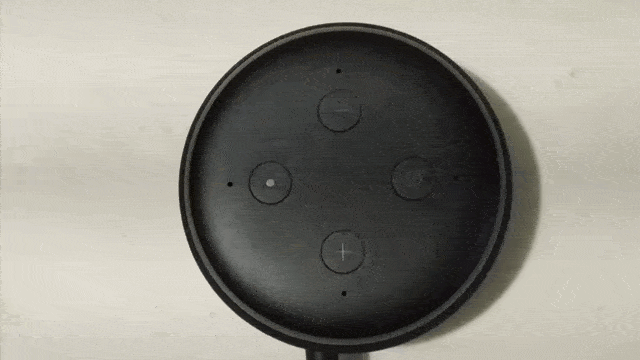
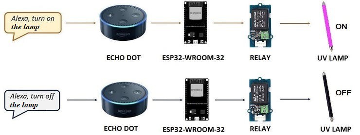
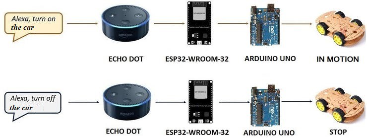
- "Alexa Echo Dot" connection with the ESP32-WROOM-32 board, to transmit voice commands to the Robot;
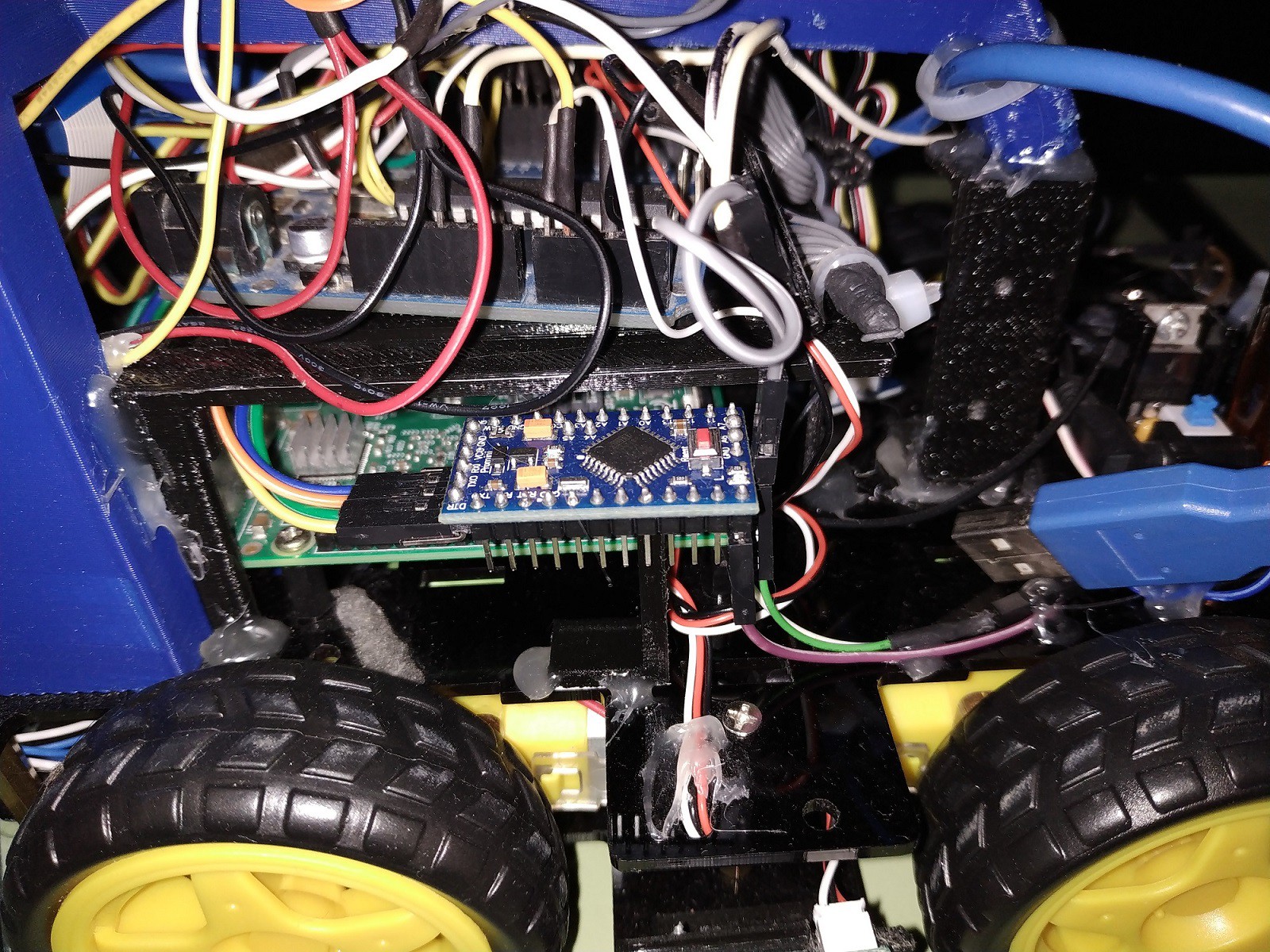
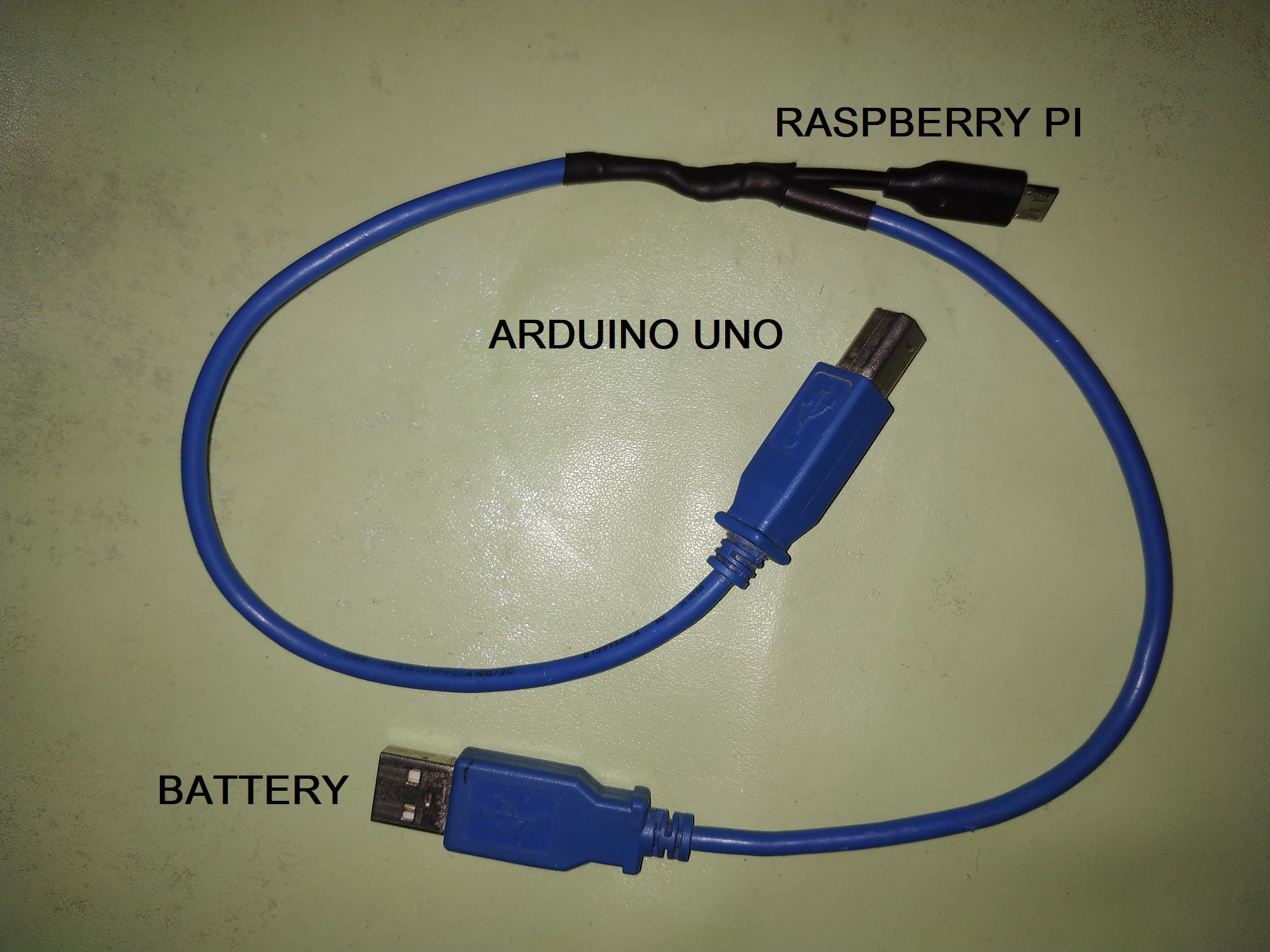
- Calculation of Neural Networks with Python to be used on the Arduino board, and to control the Robot;
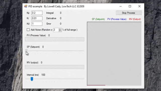
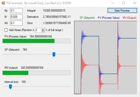
- Use of a PID Controller to control the speed and turn of the Robot; and
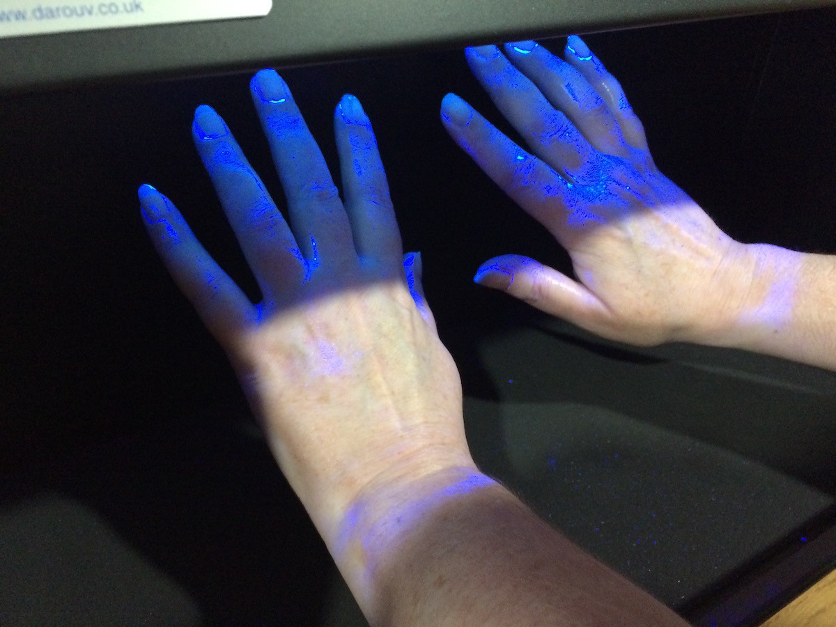
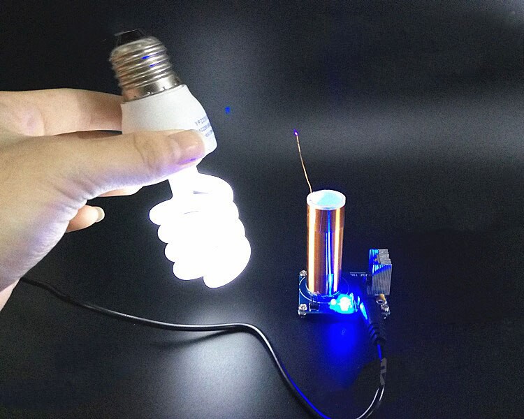
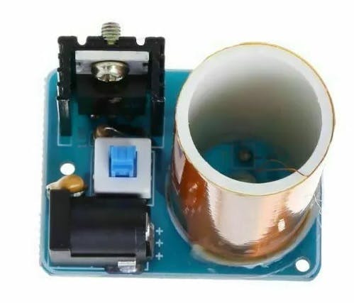
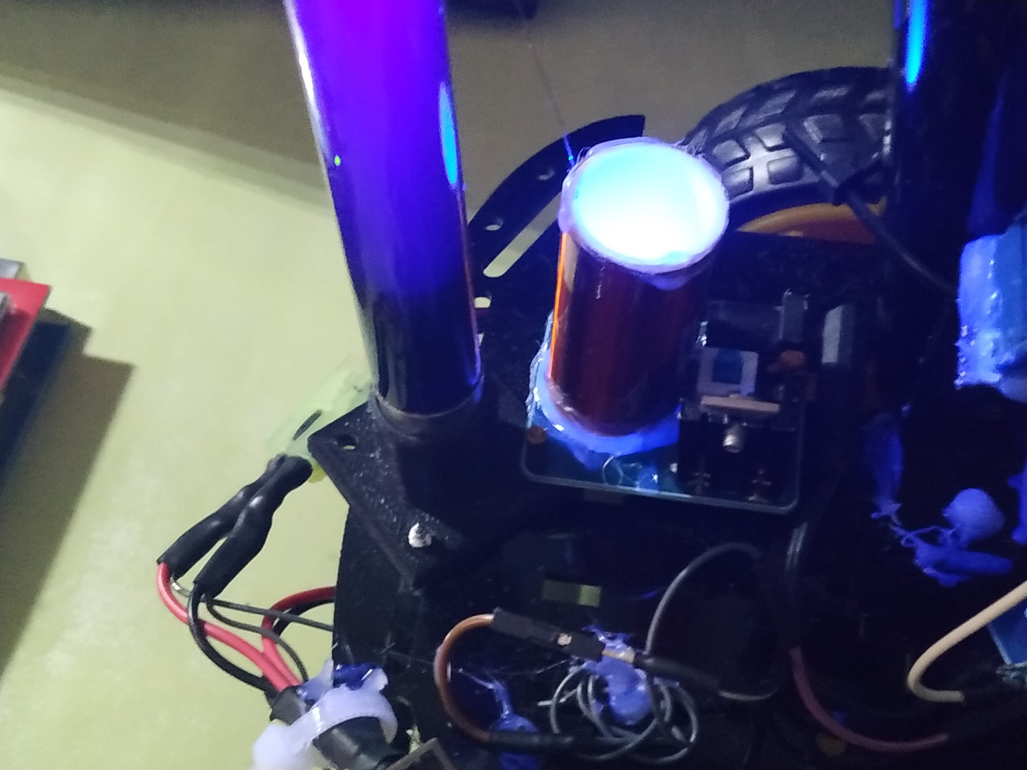
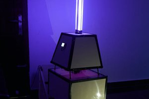
- Using of the Tesla coil to light an UV lamp.
Not in Motion Version, specific goals:
- Developing a reflector to concentrate the energy of UV lamp on an object such as backless stool;
- Making the Haar Cascade Classifier of a backless stool with OpenCV and Python; and
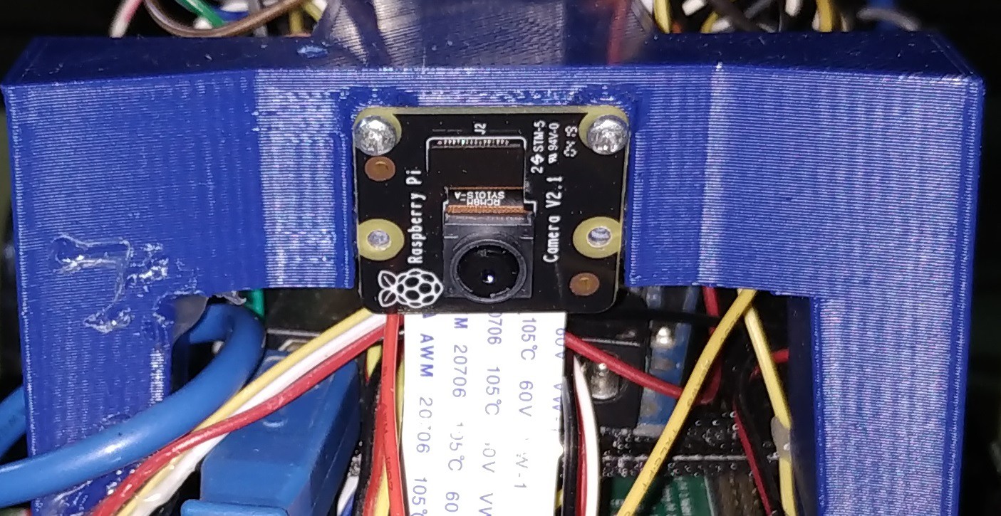
- Detecting and aiming the reflector over the backless stool using the Cascade Classifier and the Raspberry Pi board with it's camera.


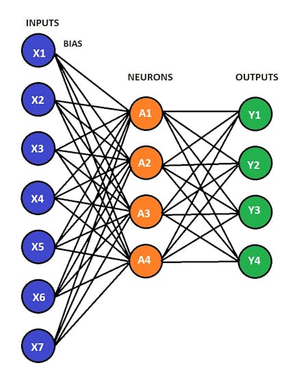
 Inputs, Outputs and Actions of the Gearmotors
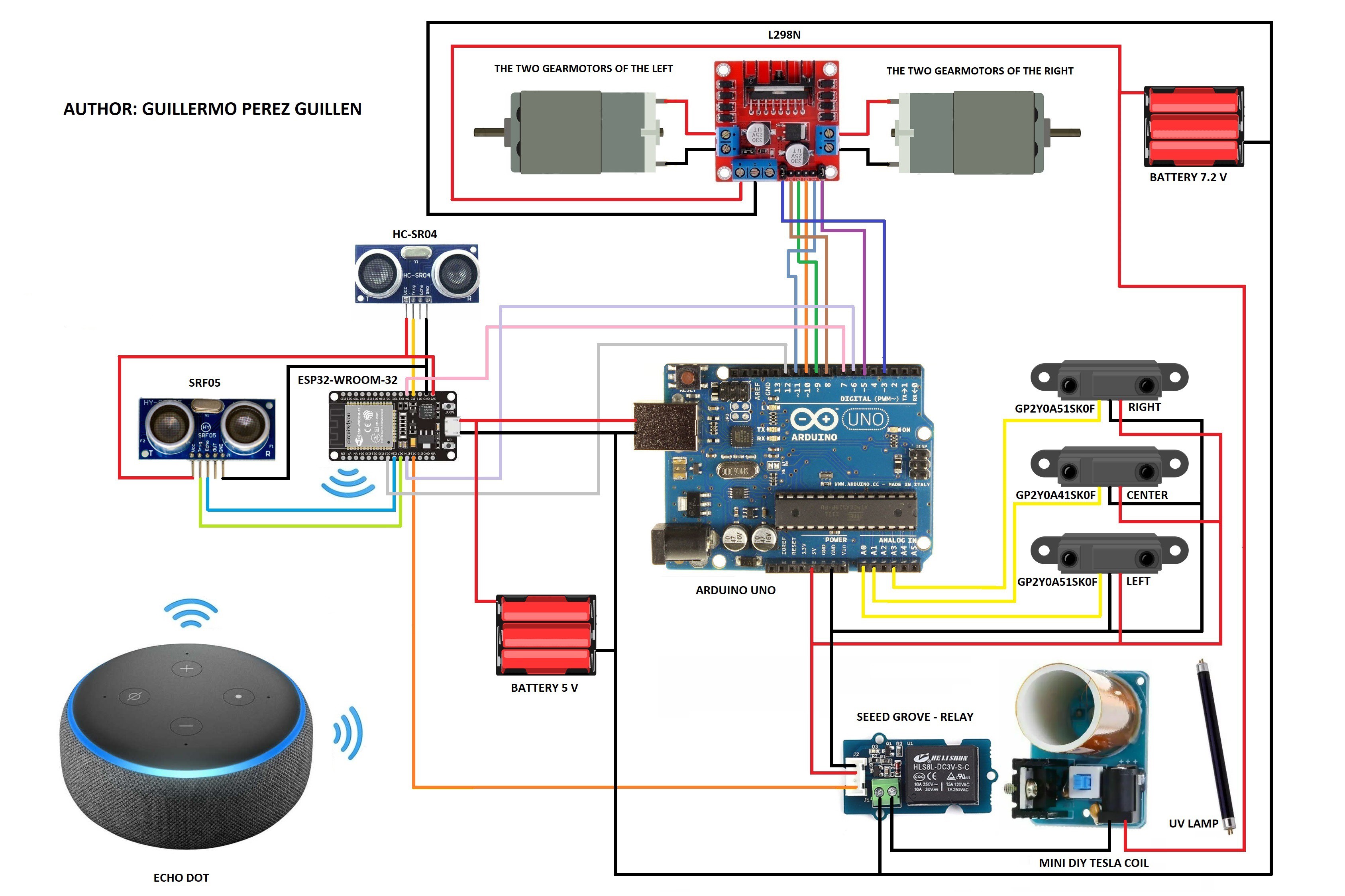
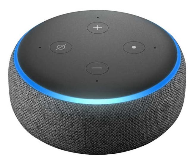 Alexa Echo Dot
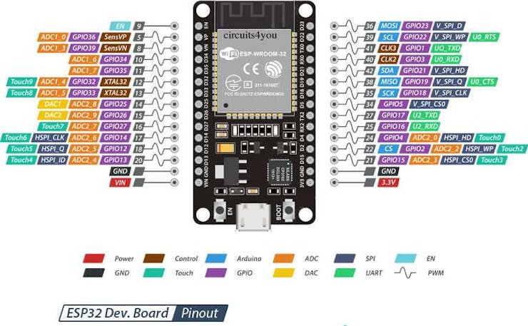

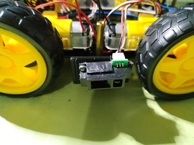
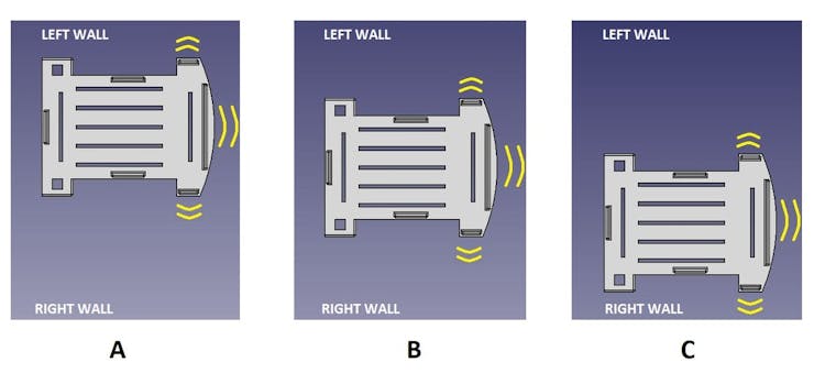
 SRF-05 Sensor
 ESP32-WROOM-32 board
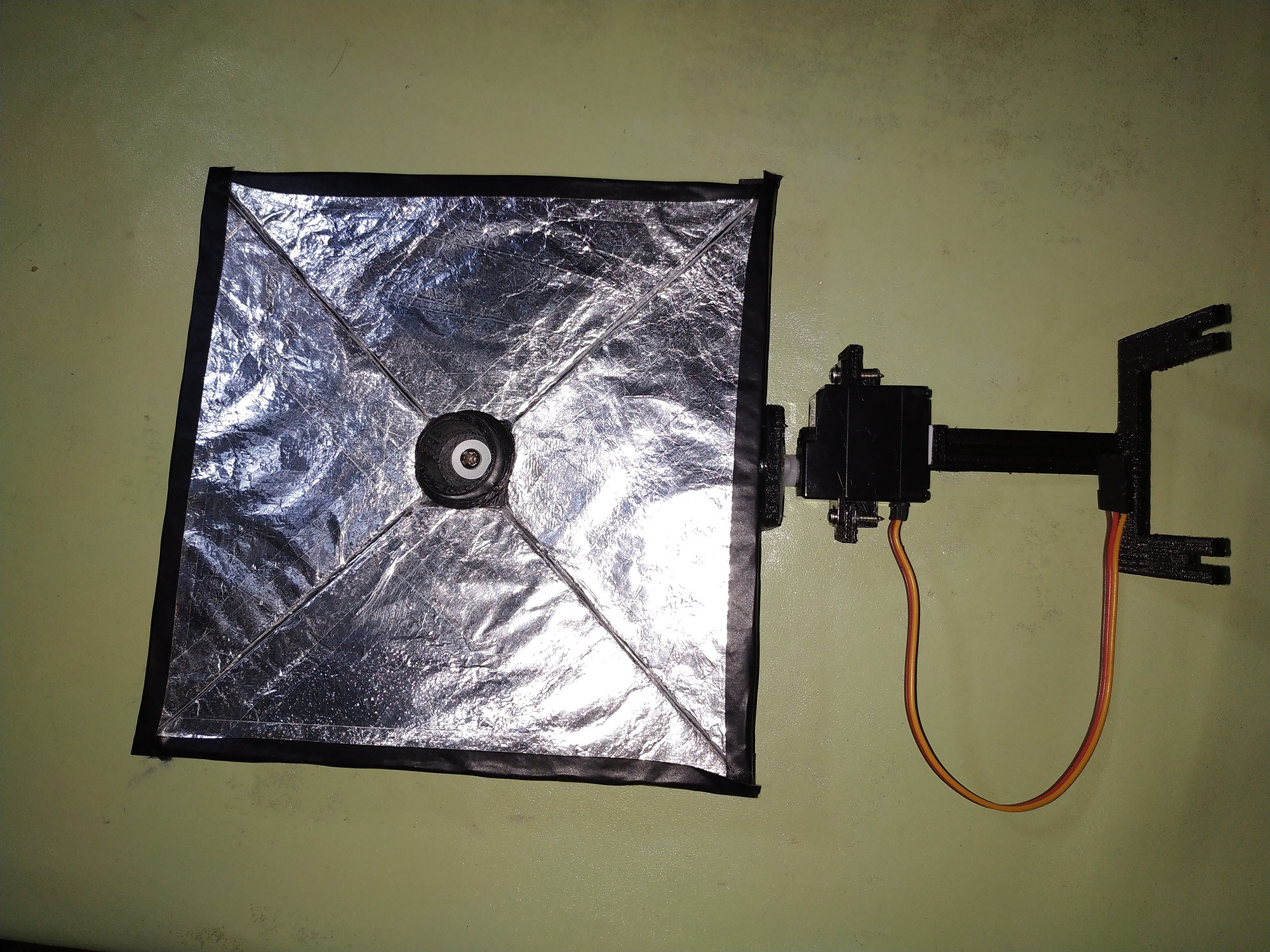
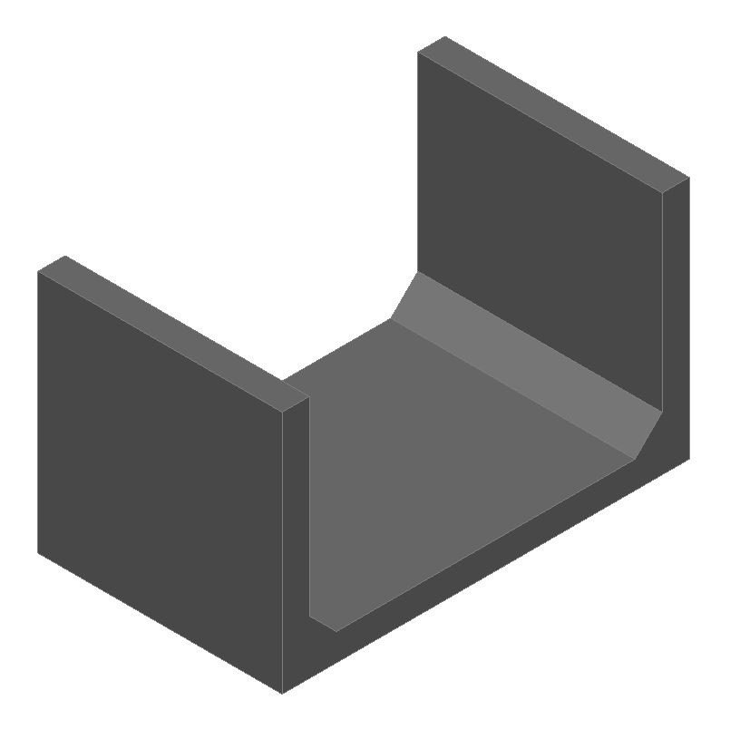
 UV lamp holder
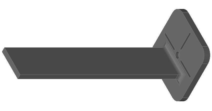
 IR sensor holder
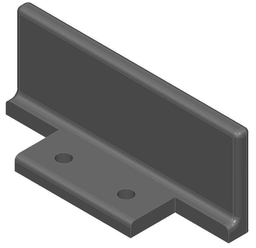

 Alex M Sunny
 M. Bindhammer
This project can help people who work at home. Today we have to sanitize all the tools and work areas, our food, the packages that are sent to us by messenger service, etc.