We developed this project in partnership with JLCPCB and Robo Lúdico School. The used board files are available for download. Download the 2 boards for projects with Arduino.

Figure A - An Arduino Board for your projects.

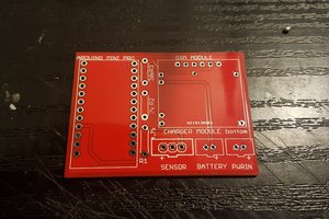
Figure B - Shield for easy connection of your sensors and other devices to Arduino.
Link to download the Arduino compatible board: https://bit.ly/ArduinoGerberFilesPCB
Link to download the shield: https://bit.ly/3fNSNRI
I made the project with JLCPCB. They released a coupon to earn 5 units of that card. The coupon is: JLC-REBE
The process is simple:
- Download the Gerber files from the project link;
- Visit the website: https://www.jlcpcb.com/PFC
- Upload the Gerber files;
- Apply the JLC-REBE coupon in the payment area.
Let's start the project!
There are often no electrical power sources from the electrical grid to power our devices in the field.
Thus, it is necessary to use a battery to power the device in the field, but the batteries have a limited charge, so they will not be able to power our device for many days.
So there needs to be a charging system for the battery, solar energy is available all day long, so we can use it to charge our battery.
So in this article, we will learn how to use a photovoltaic panel to power the battery charger, thus being able to charge the battery.
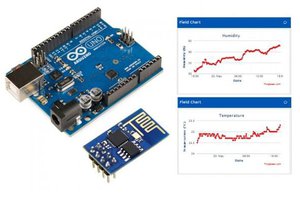
We will use the following elements: an Arduino UNO, a BMP 280 sensor, a radio transmitter, to transmit the collected data to the receiver.
So, through this article you will learn:
- Carry out the assembly of the circuit on the breadboard
- Use of the photovoltaic panel, battery charger module TP 4056, Step - Up converter.
- Make the Arduino UNO communicate with the HC 12 module
- Understand how the BMP 280 sensor works
- Understand how serial communication works with a radio transceiver
Now, we will start the complete presentation of the development of the Solar Energy project to power devices in the field.
Development of solar charging system for monitoring devices
The figure below shows the electronic scheme of the project. How does the circuit work?
The solar panel is responsible for receiving sunlight and transmitting energy to the TP4056 charger. Use a Shottky diode between the solar panel and the TP4056 module.
It is used to protect the solar panel against polarity reversal in the battery charger.
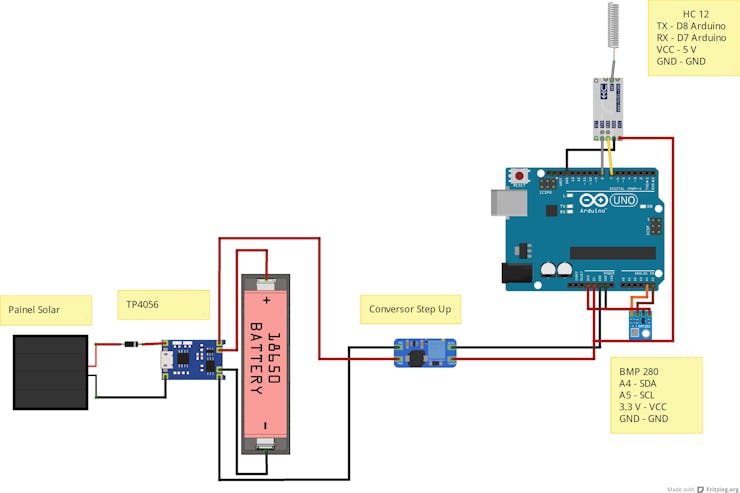
Figure 1 – Schematic circuit with the connections of the solar panel and TP4056 charger and Step Up converter.
The battery must be connected to terminals B+ and B- of the TP4056 module. This module has the IC DW01 that protects the battery against overload.
Never use an inappropriate module to charge the battery, as it may explode, be careful.
The Out + and Out – outputs are connected to the Vin + and Vin – terminals of the Step-Up converter. Figure 2 shows the model of Step-Up converters used. This model features a USB output.
_392eqtOpag.jpg?auto=compress%2Cformat&w=740&h=555&fit=max)
Figure 2 – Physical assembly of the battery charging system with the solar panel.
After assembling the charging system, we have the Arduino Uno circuit connected to the BMP 280 Sensor and the HC 12 radio module.
The BMP280 sensor uses I2C communication for data transmission, that is, it uses 2 wires for data transmission SDA (Serial data address) and SCL (Serial clock line) clock signal to send information. See the code below.
#include <SoftwareSerial.h>#include <Adafruit_Sensor.h> //INCLUSÃO DE BIBLIOTECA#include <Adafruit_BMP280.h> //INCLUSÃO DE BIBLIOTECA Adafruit_BMP280 bmp; //OBJETO DO TIPO Adafruit_BMP280 (I2C) SoftwareSerial HC12 (8,7); // RX TX float temp;int pressao,p,t ; byte TX[4];void setup(){ Serial.begin(9600); HC12.begin(9600); if(!bmp.begin(0x76)){ //SE O SENSOR NÃO FOR INICIALIZADO NO ENDEREÇO I2C 0x76, FAZ Serial.println(F("Sensor BMP280 não foi identificado! Verifique as conexões.")); //IMPRIME O TEXTO NO MONITOR SERIAL while(1); //SEMPRE ENTRE NO LOOP }}void loop() { temp = bmp.readTemperature();...
Read more »
 igorfonseca83
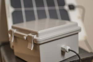
 CLANDESTIGN
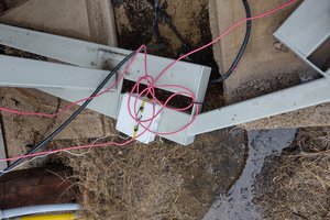
 Kody Alan Rogers