 Sergio Ghirardelli
VIDEO PRESENTATION
Lithium battery pack needs a BMS (Battery Management System).
The main functions of a BMS are:
- To protect the cells against overvoltage
- To protect the cells against undervoltage
- To save the cells in case of temperature out of the ranges
- To balance the cells
A Smart BMS has these additional functions:
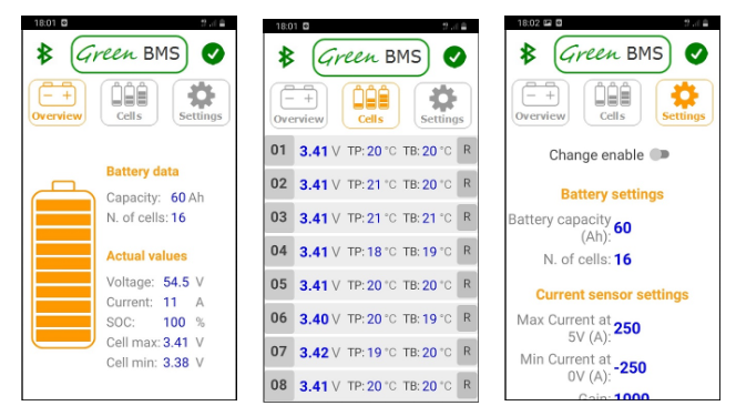
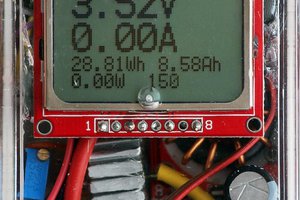
- To consent the monitoring of the battery pack
- To consent the monitoring of each cell
- To consent to perform parameter settings
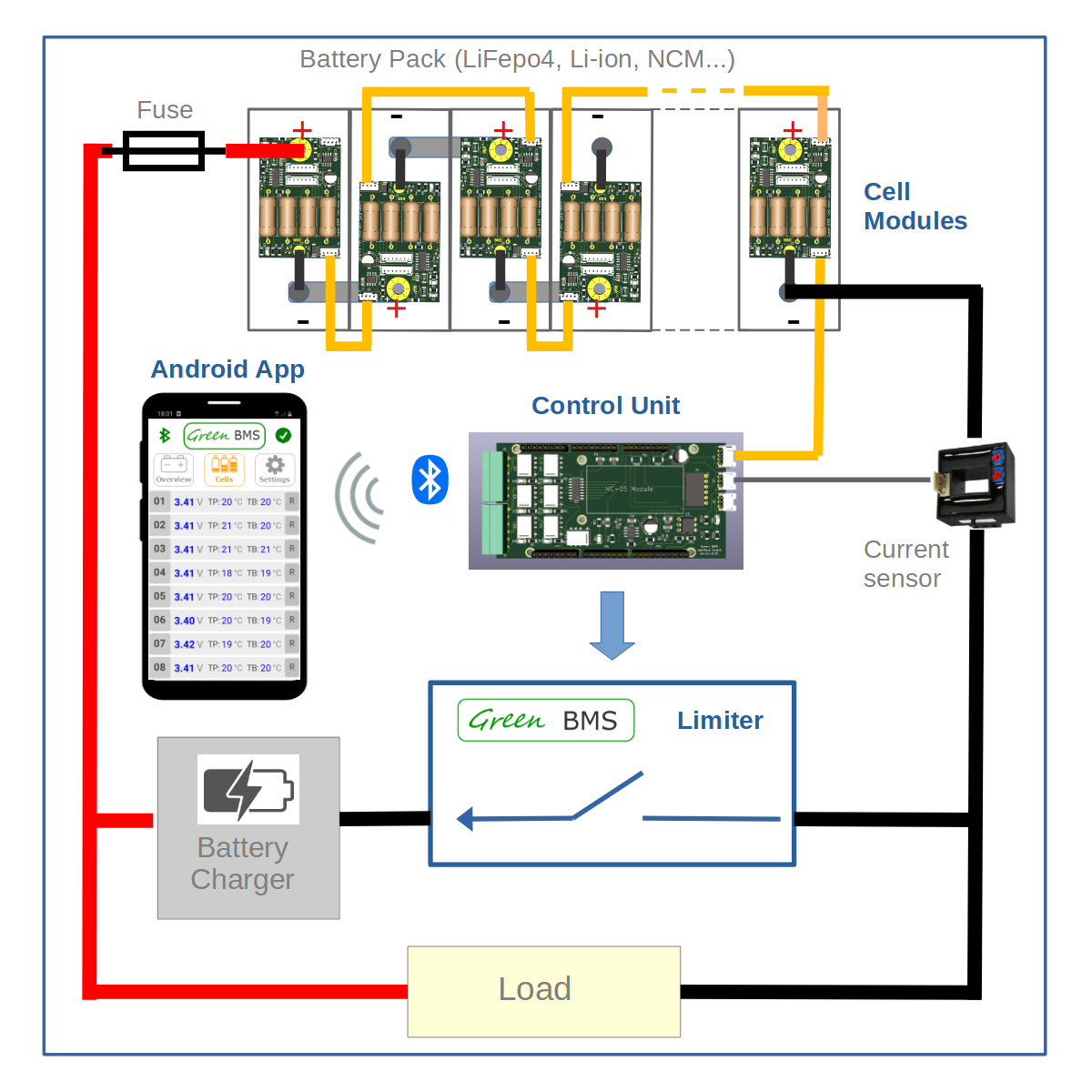
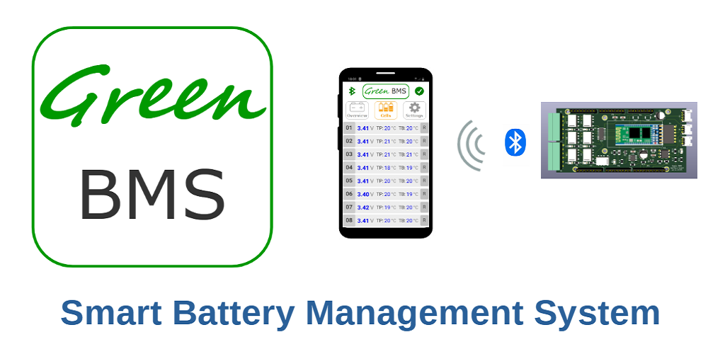
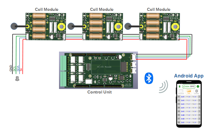
Green BMS is a Smart BMS and it includes four main components:
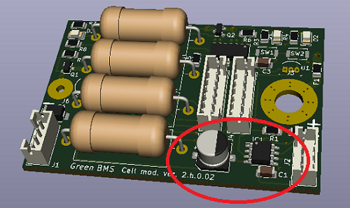
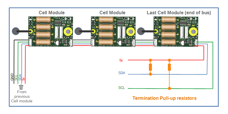
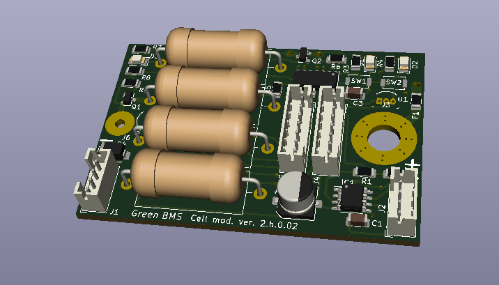
1. Cell Module
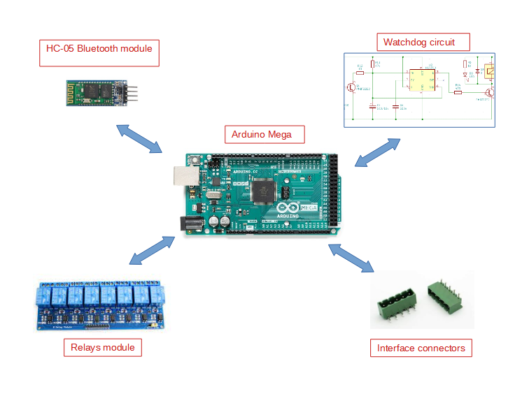
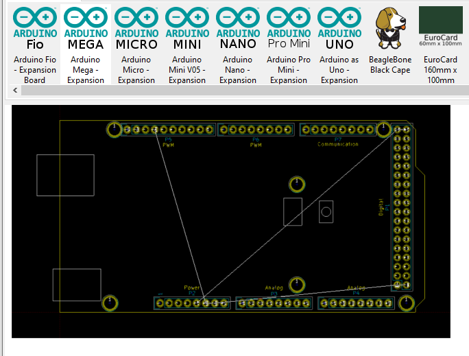
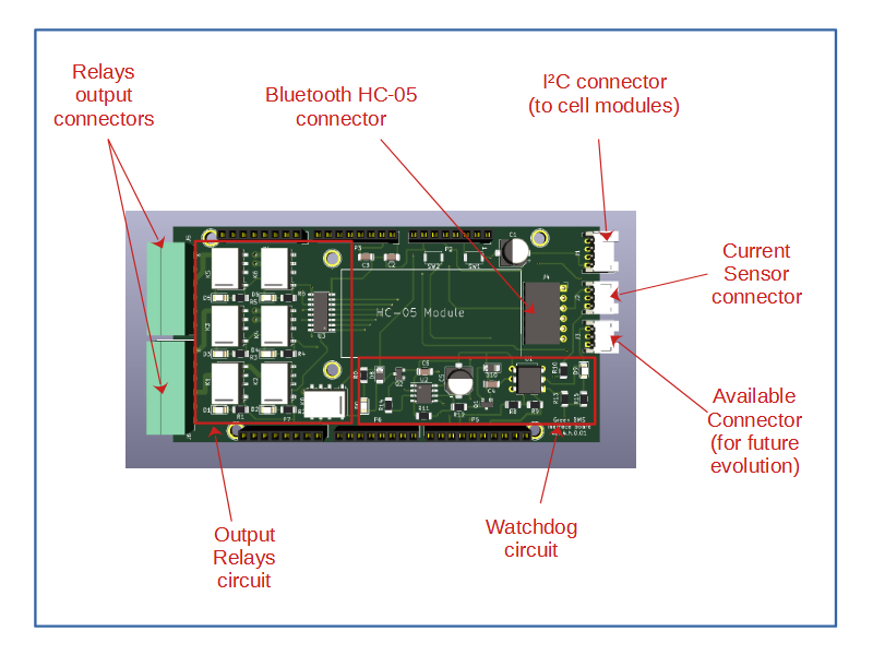
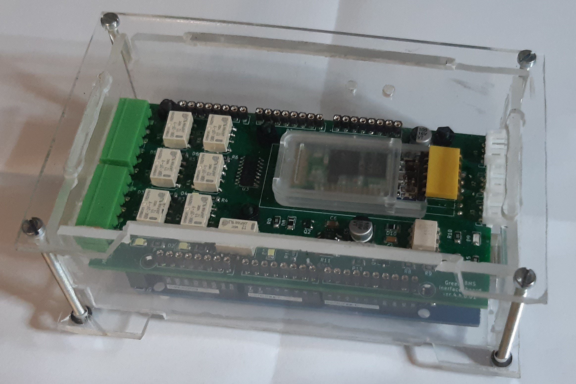
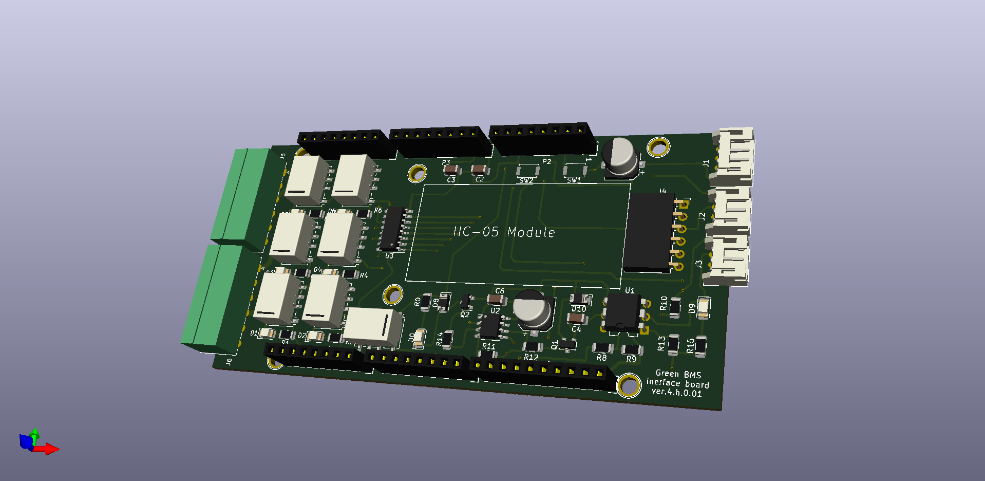
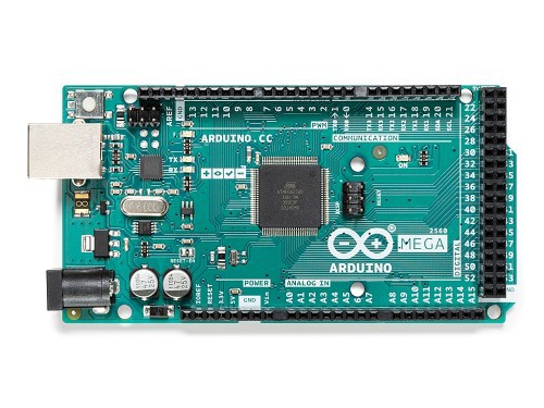
2. Control Unit
3. Limiter
4. Android App
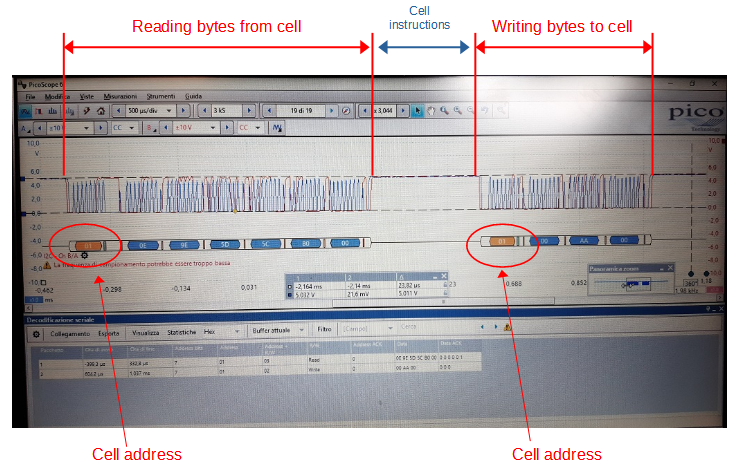
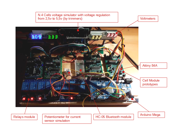
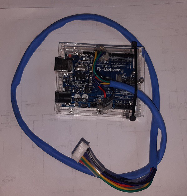
The voltage and the temperature values of each cell are acquired by the relevant Cell Module (Attiny) and sent to Control Unit (Arduino Mega) through a serial I2C line.
Control Unit starts or stop charging (by output relay) through Limiter, that includes a power relay for opening or closing the charging circuit. Control Unit can also start or stop discharging by output relay.
Balancing current: up to 1,2 A (adjustable by parameter).
When just one cell of the pack is balancing, Control Unit activates the current limit function inside the Limiter (the charging current is limited to 1A).
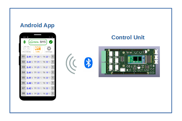
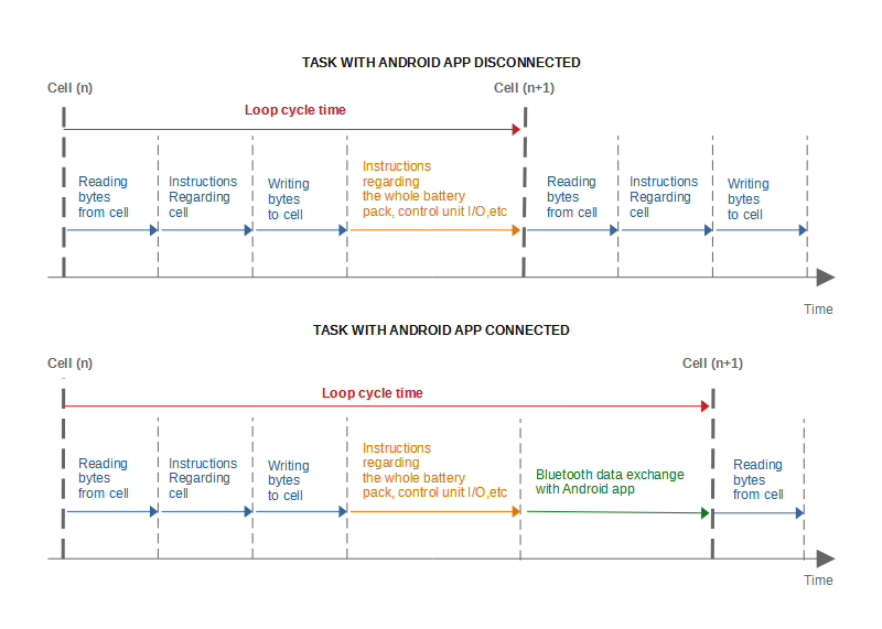
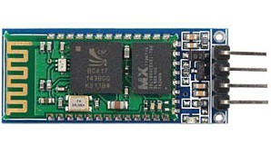
Control Unit can be connected (bluetooth) with a Smartphone by Green BMS App!
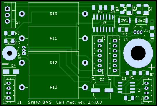
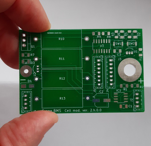
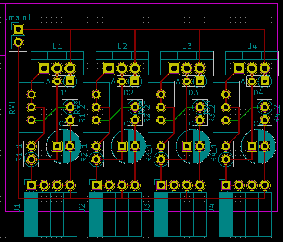
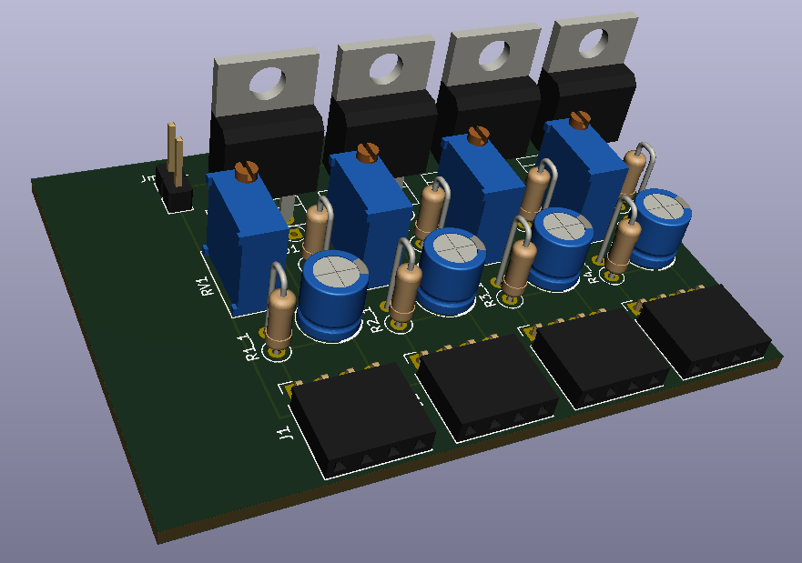
CELL MODULE
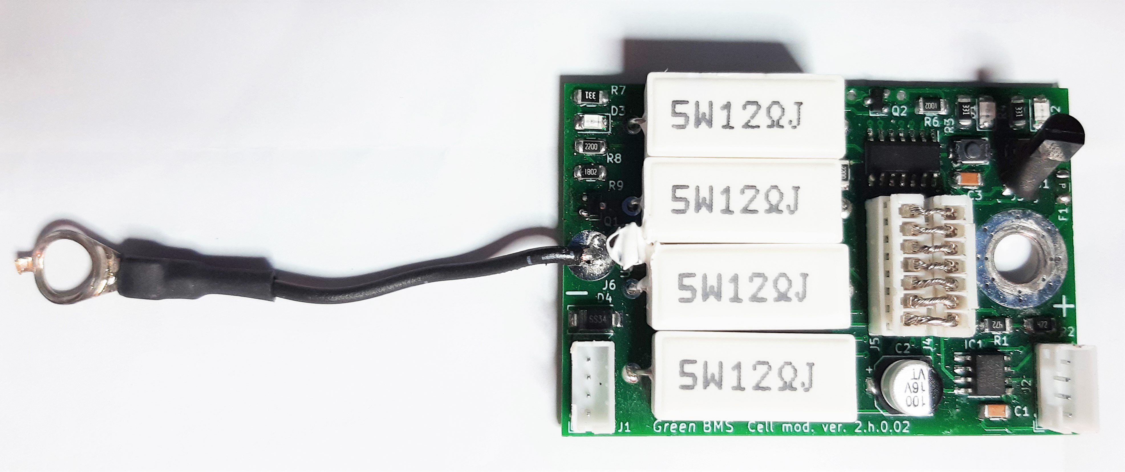
Cell Module description is available on this page: https://hackaday.io/project/181453-green-bms/log/198376-cell-module
CONTROL UNIT
Control Unit description is available on this page: https://hackaday.io/project/181453-green-bms/log/198414-green-bms-control-unit
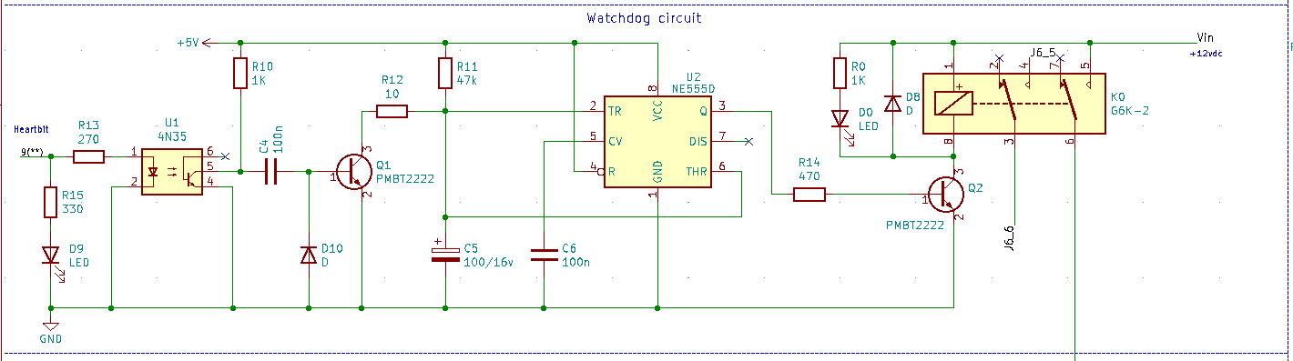
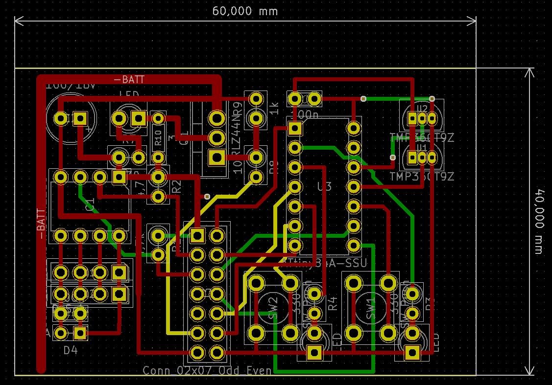
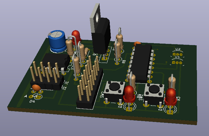
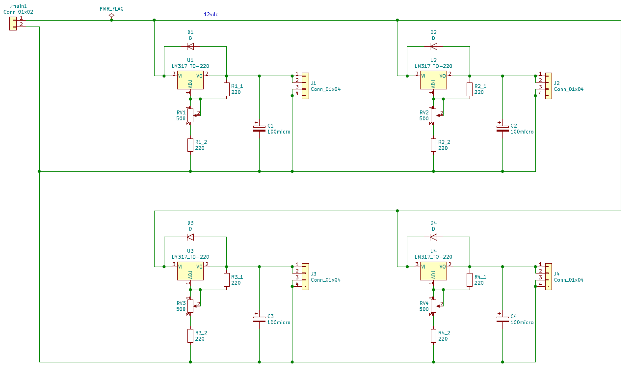
LIMITER
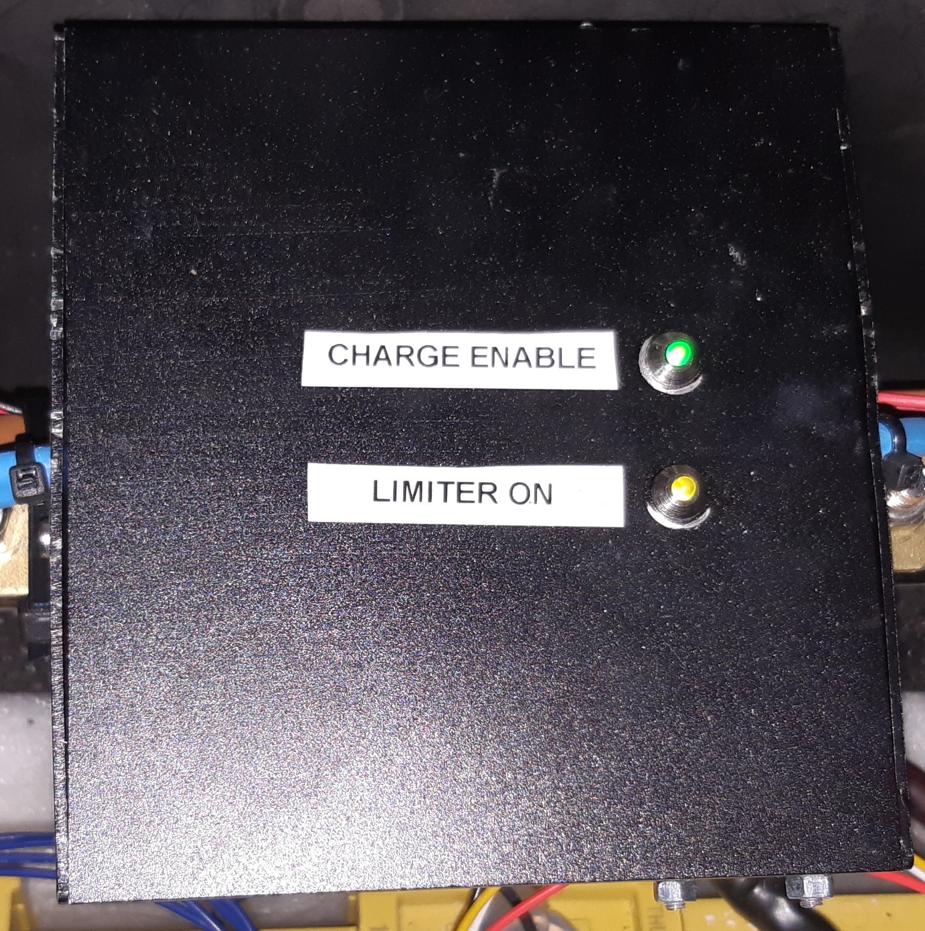
The BMS Battery Management System Limiter is described here: https://hackaday.io/project/181453-green-bms/log/198378-limiter
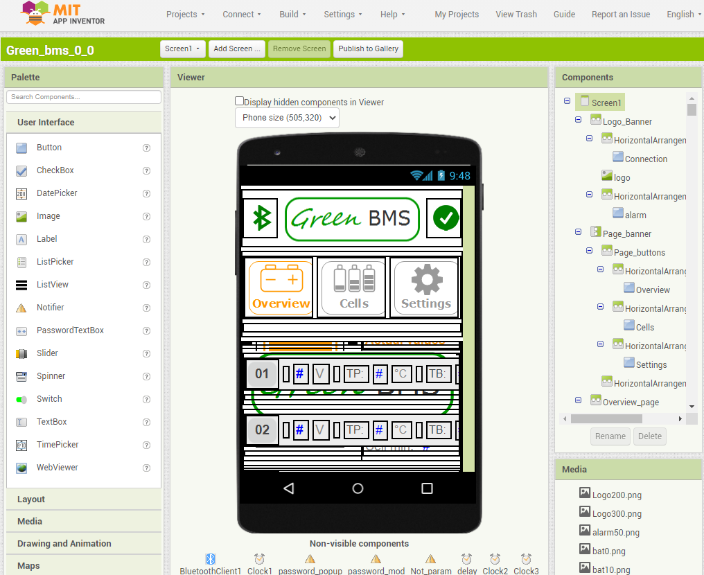
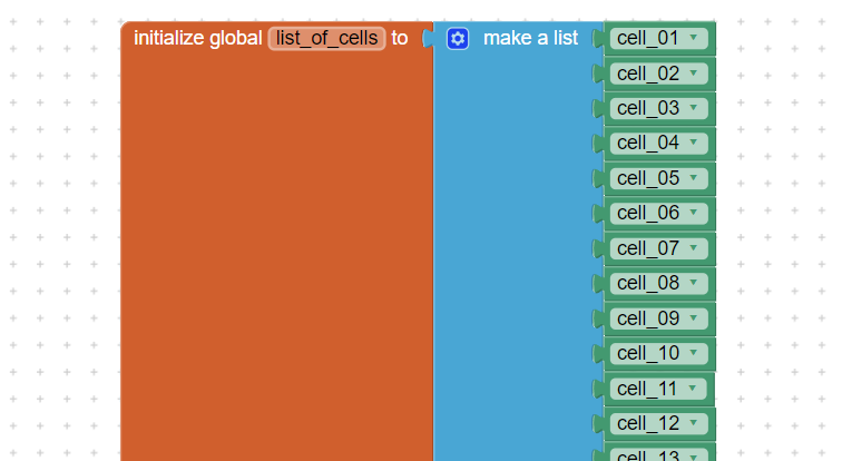
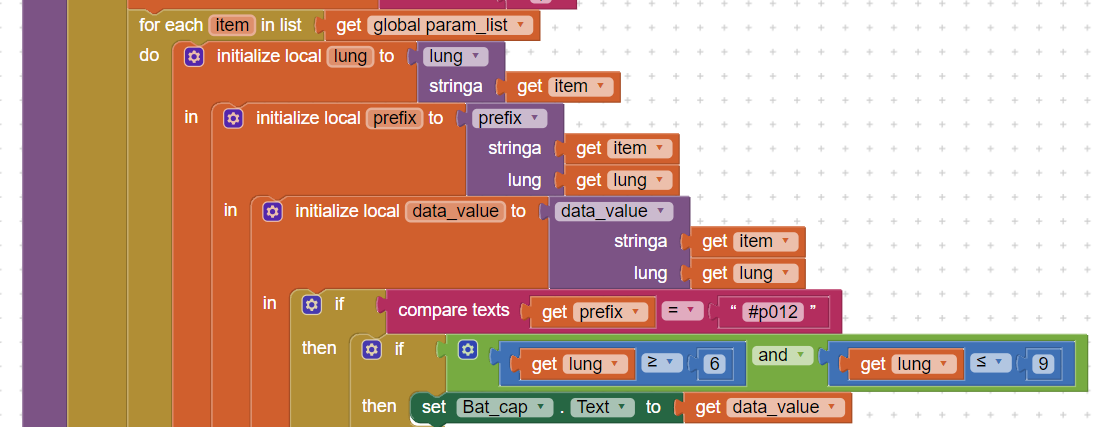
GREEN BMS ANDROID APP


Green BMS Android app is described here: https://hackaday.io/project/181453-green-bms/log/198377-green-bms-android-app
OPENSOURCE HARDWARE CERTIFICATION
Green BMS has been certified as open source hardware by the Open Source Hardware Association, with the UID: IT000007.
LICENSE
This work is licensed under a Creative Commons Attribution-ShareAlike 4.0 International LicenseCreative Commons Attribution-ShareAlike 4.0 International License.


 mr.jb
mr.jb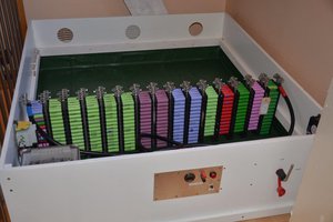
 Michel Kuenemann
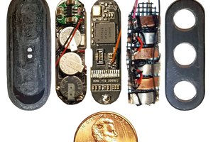
 Curt White
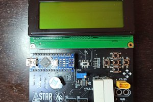
 STAR
STAR