0%
0%
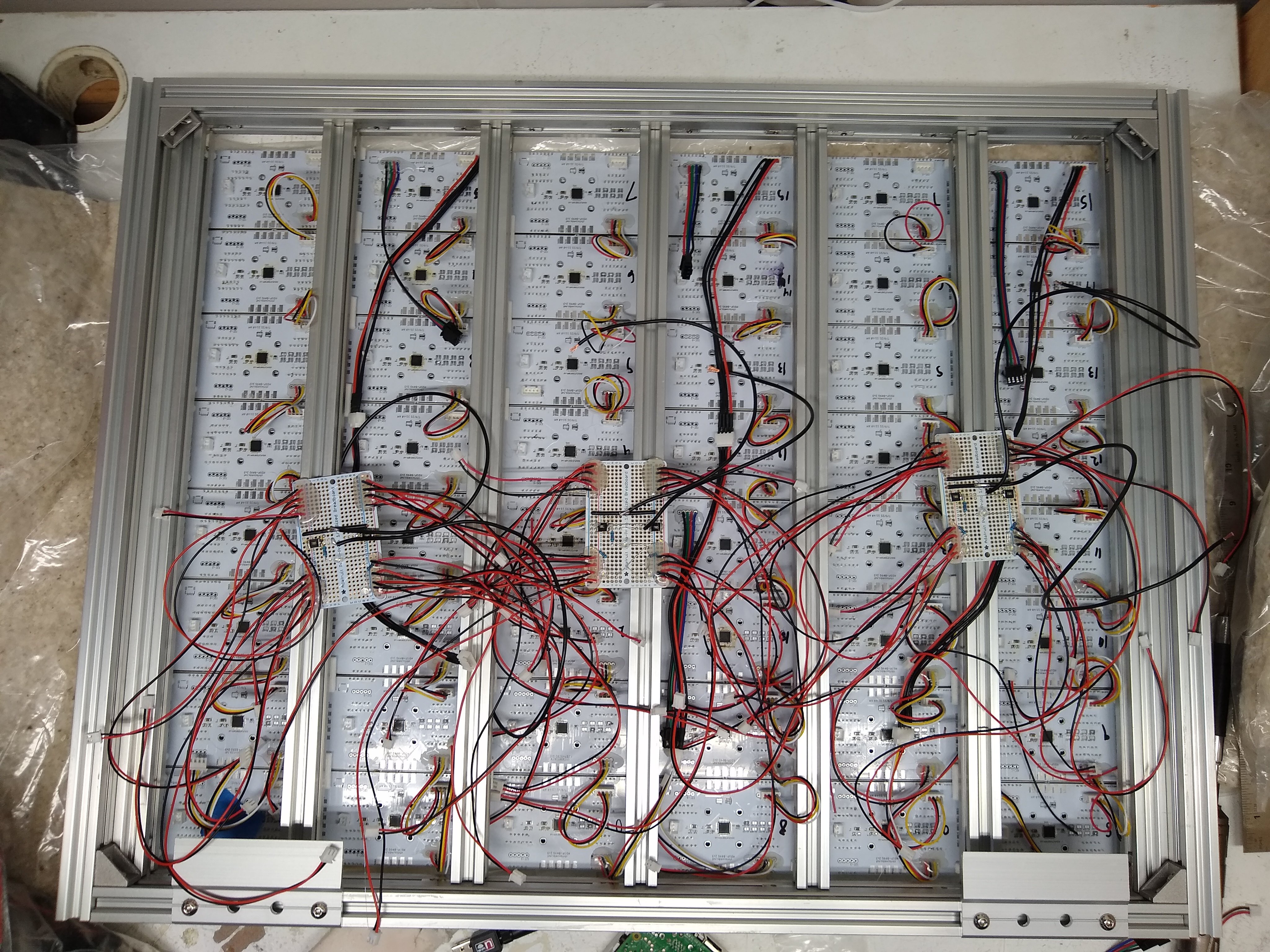
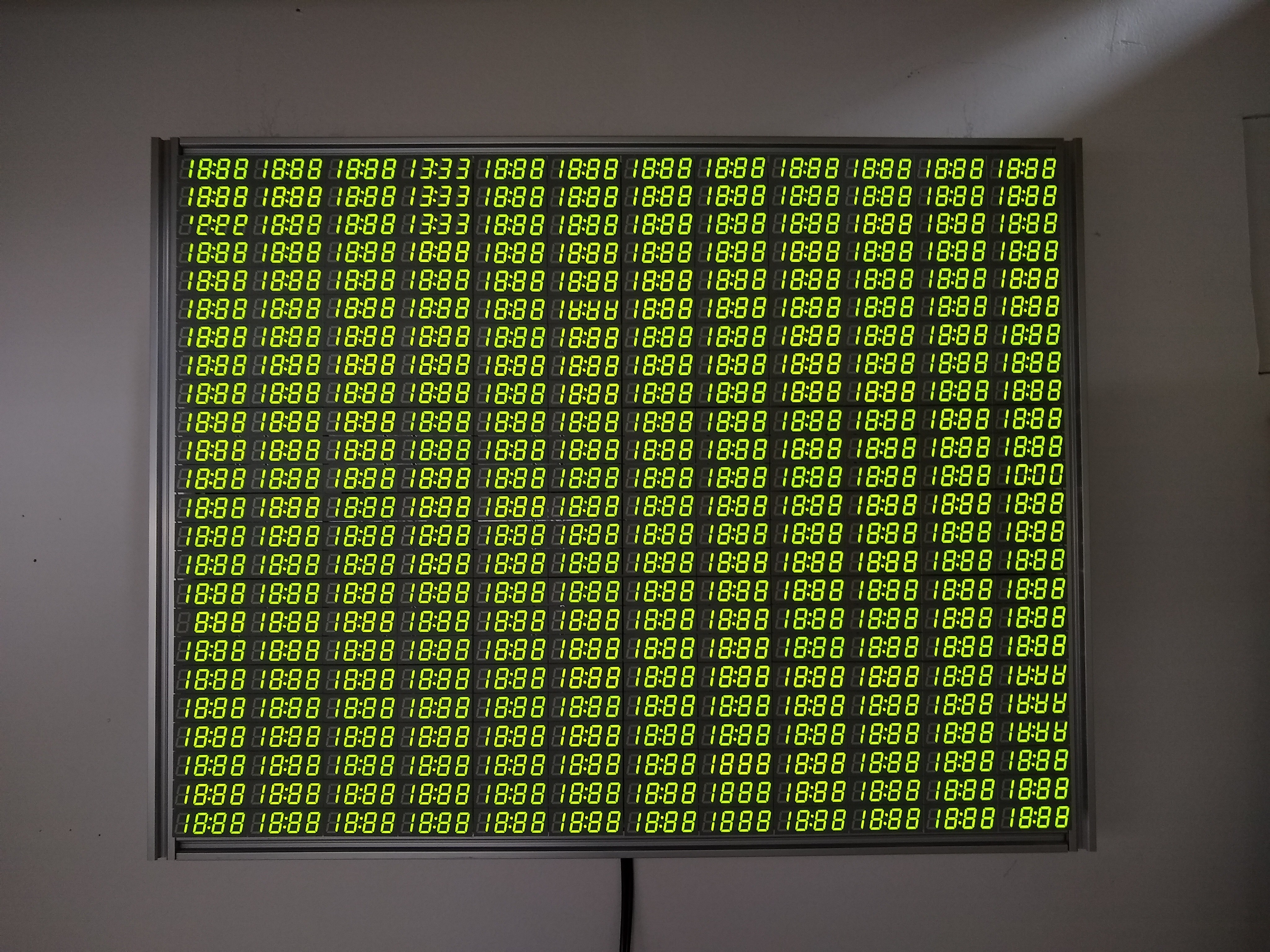
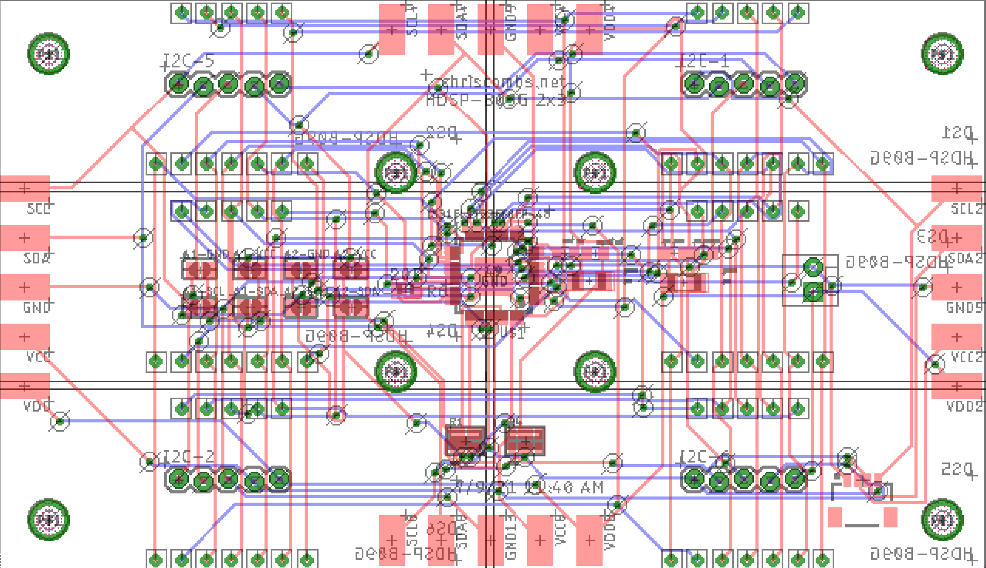
7,200-segment, 1,152-digit 7-seg display
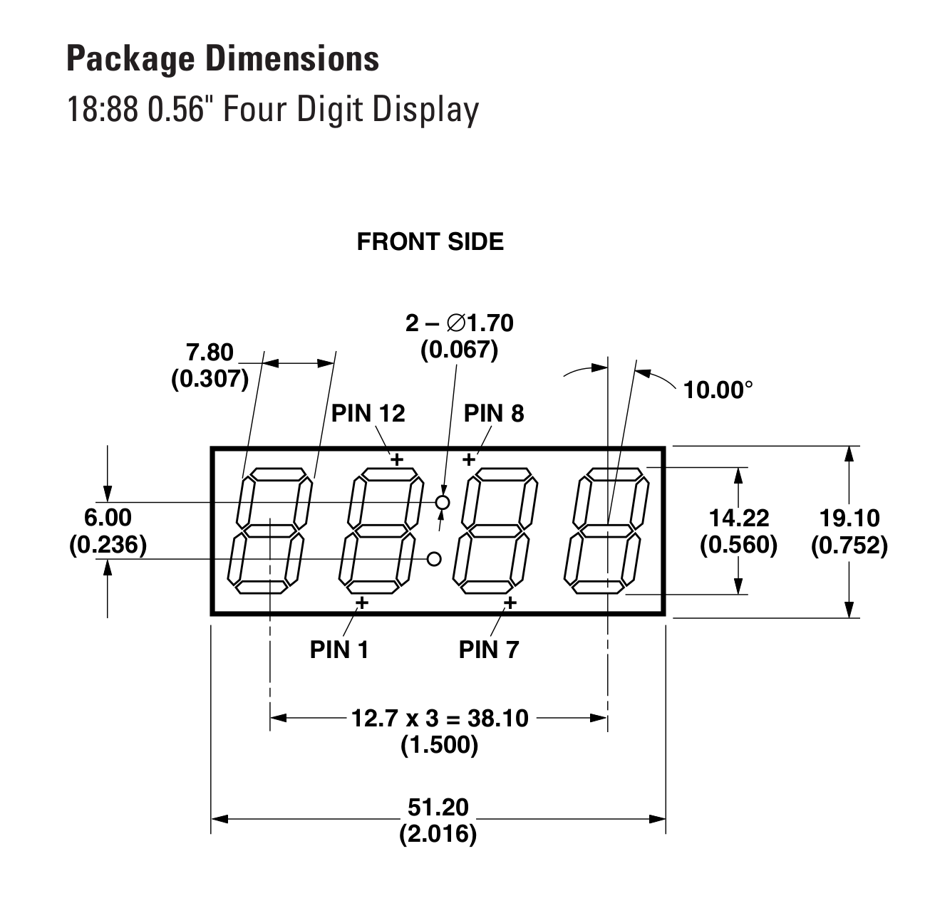
48 display controllers over three I2C buses; 288 four-digit 18:88 clock displays (25 segments per display); full 8-bit PWM grayscale control
 Chris Combs
Become a Hackaday.io member
Already have an account? Log in.
Just one more thing
To make the experience fit your profile, pick a username and tell us what interests you.
Pick an awesome username
hackaday.io/
Your profile's URL: hackaday.io/username. Max 25 alphanumeric characters.
Pick a few interests
Projects that share your interests
People that share your interests


 Stephen Holdaway

 Jeremy Gilbert
The largest project I had done involving pulling 24 buttons to a Arduino Micro. I used 74HC165Ds and pull in 3 bytes (8 * 3 bits) each loop.
I have also used a SPI display, and being 128*64 you need to push 1KB of data each loop. Even with these constraint it can still manage 80 fps.
Given how you effectively used 288 display modules, you can use maybe 288 of 74HC164 and then wire all the four anodes together (perhaps through power transistors too).
This approach mean however that you need to push 288 bytes EACH time you want to update a digit, which might mean that the digit refresh is slow and the effect (of rapidly switching between four digits) will be very noticeable.
A very unnoticeable 4-digit-display might need to be done with a FPGA. My classes asked me to use a ARTIX-7, which is able to drive the 8 segments quickly enough that no camera can tell that they are rapidly switching on or off. The code got it around 250KHz I think.
Alternatively, just use a immense amount of independent 8 segment displays and push 1152 bytes each cycle (much like the 128*64 screen). However, wiring/soldering them up can be a nightmare.
Both way however require sacrificing grayscale. Unless you want something like 2-bit grayscale & 20 fps. 20 fps is okay, although not a very fast display.
From the video looks like you are doing some decent fps, although the lag between the three chunks is very noticeable (half a second), considering that I2C is a very slow protocol indeed (100KHz). Meanwhile SPI can go up to 1MHz even on a simple device like ATmega32U4.