 maloneth4
AUTONOMOUS FIRST TEST: Testing all moving parts successfully.
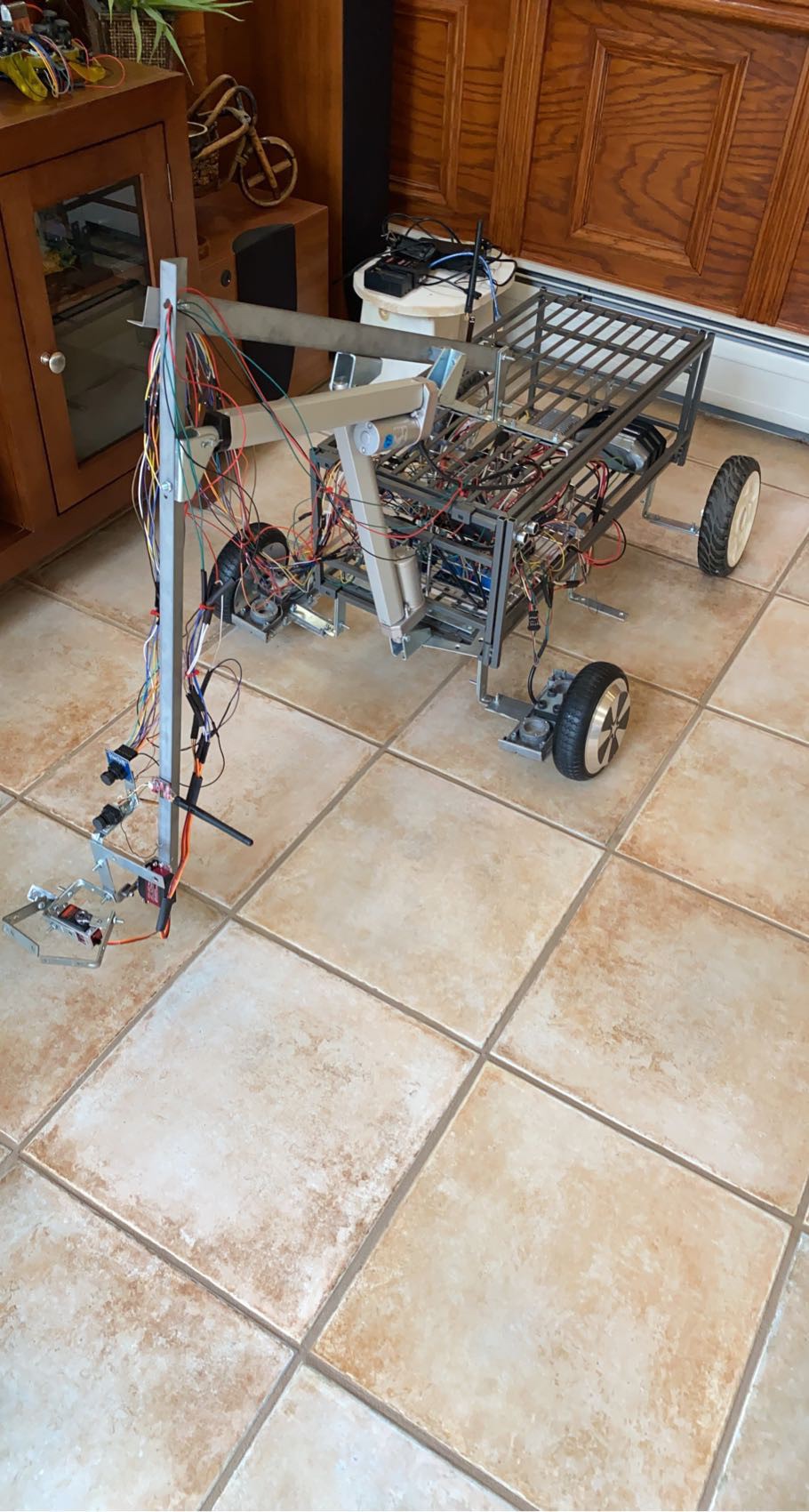
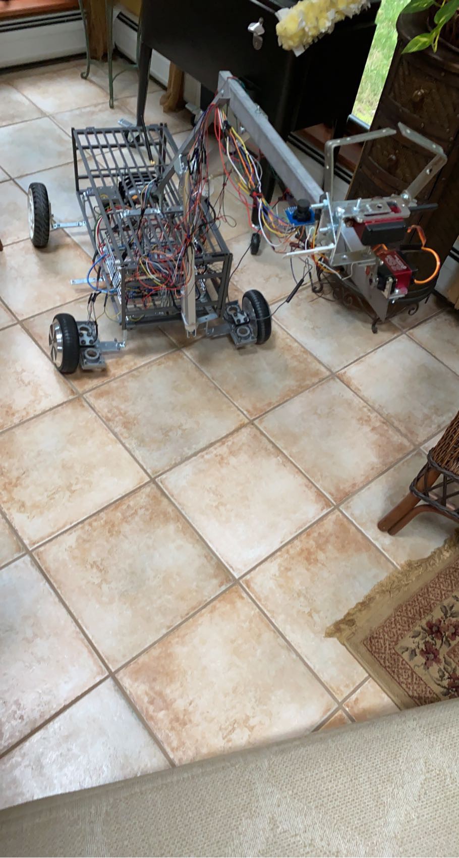
ABOUT THE ROBOT:
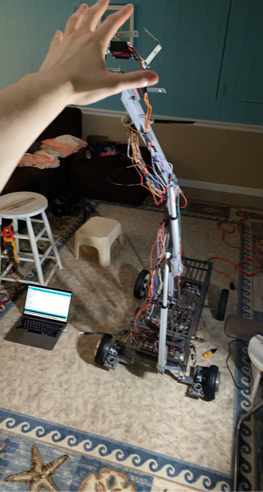
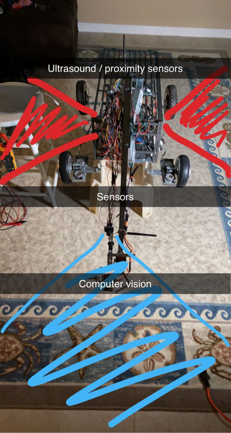
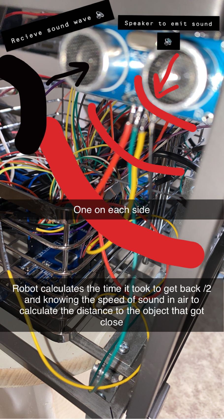
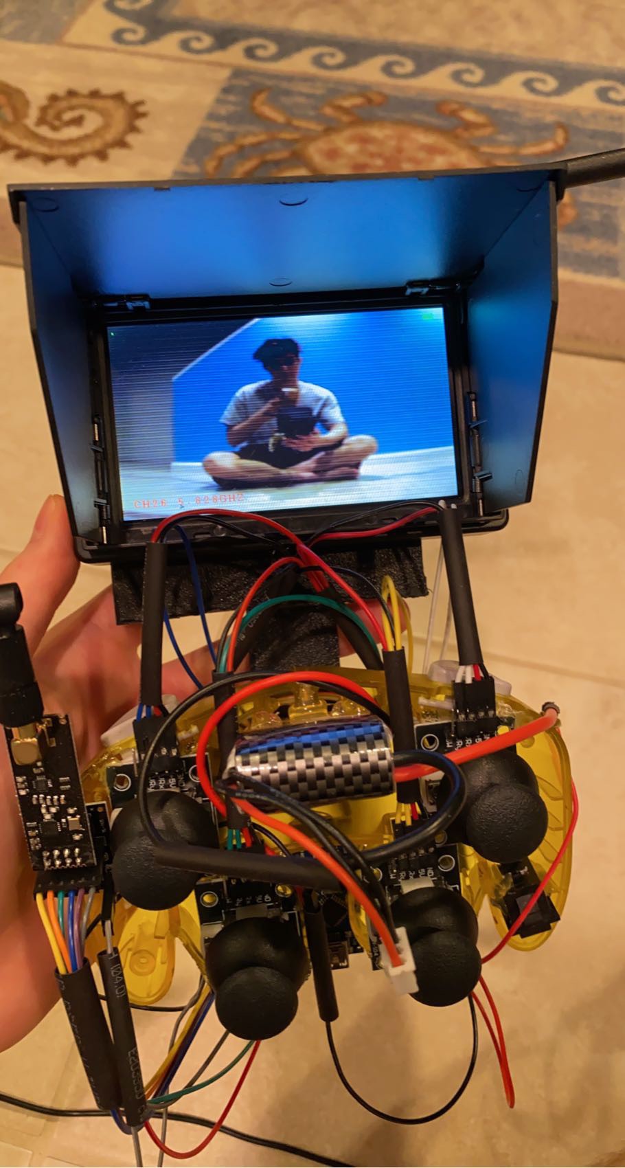
Made by myself, from June 2021-August 2021 this is the first version of my helper robot. In addition to the remote controls, it will use its same camera module for computer vision/AI & distance ultrasonic sensors to help it navigate autonomously in the real world & being able to track and follow specific objects have it do work on its own by itself.

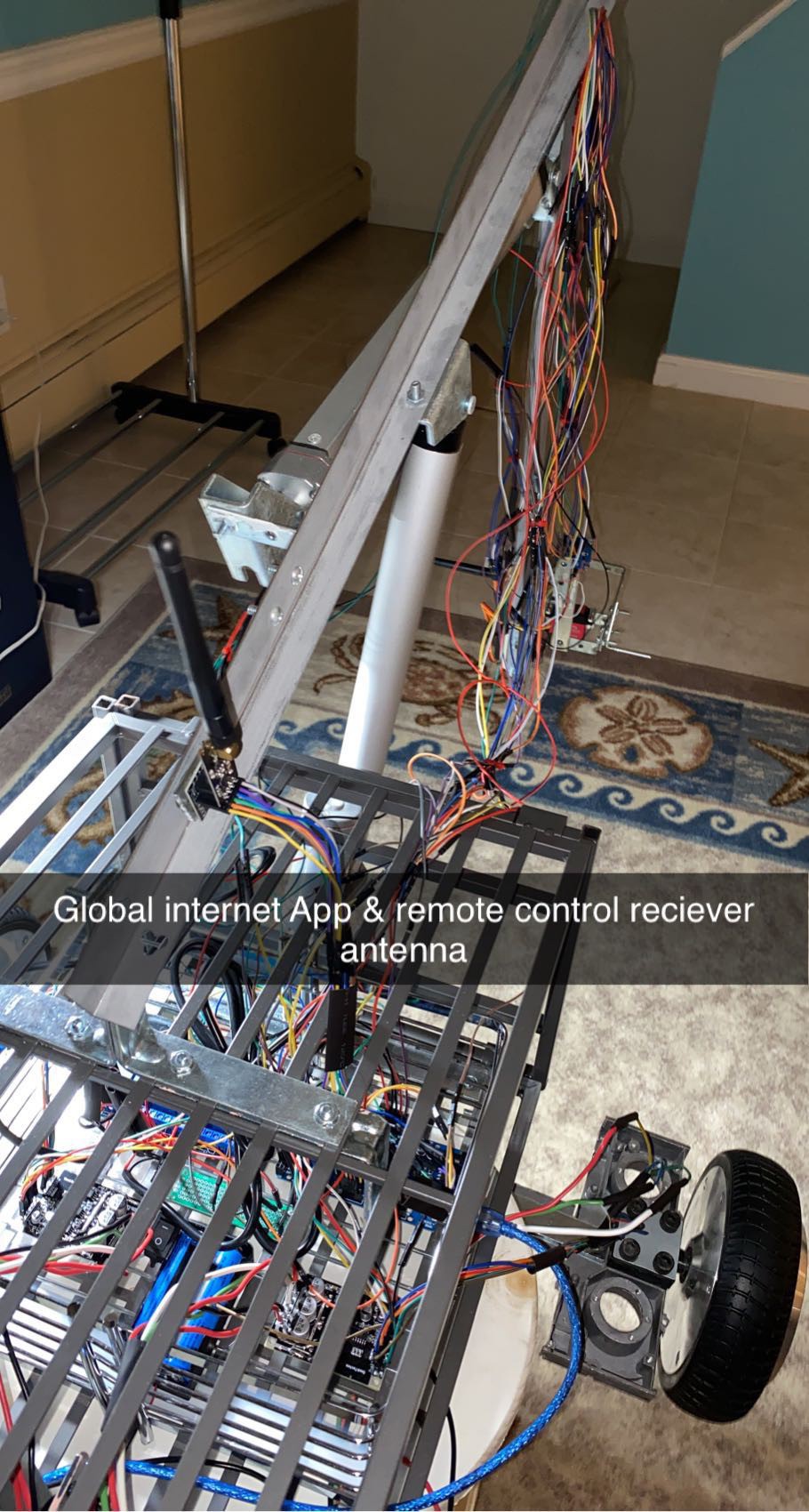
The best applications for this are cutting grass/ landscaping, shoveling snow, raking leaves, any work common people typically do that is time consuming and boring. Or just being there as an extra hand / helper to support others needs. It can transport & deliver items, and help you carry cumbersome items. Of course, the robot can be used as way to keep people safe to remotely do any dangerous tasks. I am currently working on an app in addition to the physical controller, that lets anyone, anywhere around the world use their smartphone as the controller with an internet connection.


FINAL THOUGHTS:
I made this robot to be a very sophisticated, highly versatile, yet, cost effective helper using scraps like random brackets and a steel shoe rack I had at home. I only had just enough within my budget to afford all the electronics that costed me around $500 USD. (The linear actuator arm motors were the most expensive thing by far). I originally thought of this thing being more like a tank and being more-so focused doing outside work where tank tracks really excel. As a final version of this robot, just a mere sketch, I want this robot in the future to be more well protected by some light weight armor, a larger battery for even longer run times for more work to be done, to fix its hand to pinch better and to not be a random bracket I found at...
Read more »
 Roger
Roger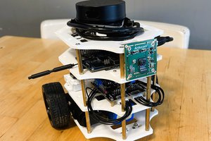
 TripleL Robotics
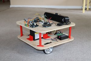
 Mike Rigsby
 Russell Cameron