 Hari Wiguna
It all started with this remnant CAT5 ethernet cable.
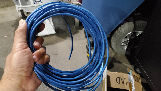
As you know, inside are six solid (22AWG?) wires.
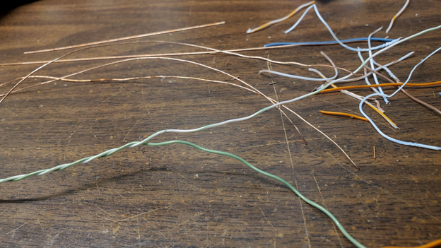
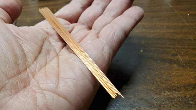
After completely stripping away the insulation, I straighten them by clamping one end on the vise and pulling the other end until the wire stretches and become very straight.
To hold the LEDs while I solder them, I lasercut a jig out of remnant cardboard. Blue tape works great for temporarily holding the wire in place while I solder the LEDs.
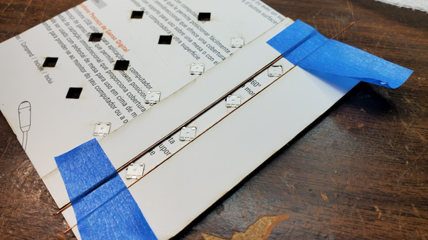
This is the result of much contemplation while driving. Rotating the WS2812B 45 degrees allow me to solder one solid wire to connect all the positive pins of the LEDs, another solid wire to connect all the negative pins, and the data pins from one LED is connected to the next using a short wire WITHOUT crossing any other wires!
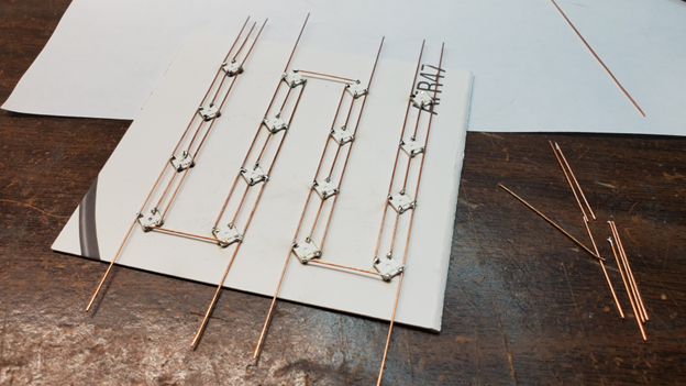
Also note how LED chain changes direction from one “pillar” to the next. This is to avoid having to have “flying” wires from top of pillar to bottom of next pillar. Instead the data chain goes up, across, down, across, up, across, down.
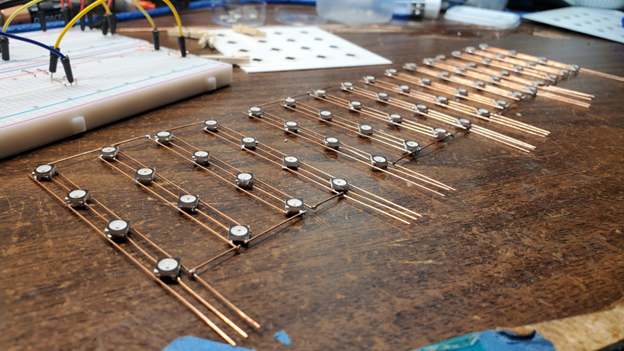
I could have also do this trick when going from one layer to the next, but I decided having the 4x4 layer identical would minimize error and the connecting wires would be on the bottom and makes the sculpture more interesting.
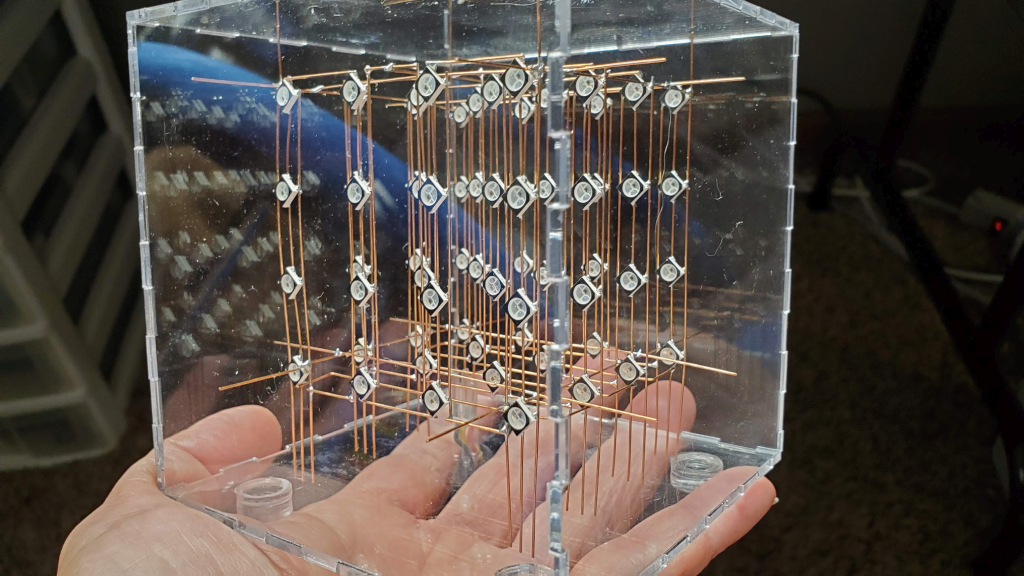
Finally, I wanted the cube to be "floating" in the middle of the laser cut Acrylic case, so I kept the extra long leads and use them to position the cube in the middle of the case.
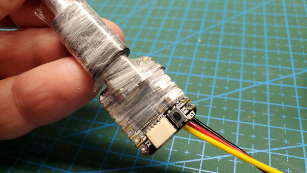
Since we only need ONE data pin to drive the whole cube. I decided to use a QT Py running CircuitPython. I powered all the LEDs using a 2A wall wart and plug the QT Py to my laptop so I could program patterns and immediately see the effect.
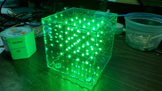
I'm still too chicken to turn all the LEDs to white, but surprisingly the cube is working fine displaying all sorts of colors simultaneously on all 64 LEDs without any extra capacitors anywhere!


 Jiří Praus
 Grant Stankaitis
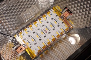
 Jan
Jan
 Rich Morrissey
Do you have STL file for your jig you can share here Hari? Thanks.