There are several goals for the project:
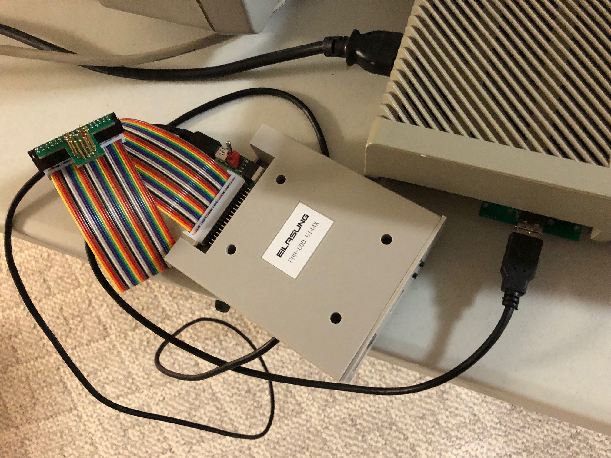
- Connect the Gotek floppy drive emulator to the Atari ST so that it can read and write emulated floppy disks.
- Do not irreparably damage the original Atari ST. IMO these old computers deserve to be maintain as closely as possible to the original design. Some solutions exist for the problems listed below, but they involve bending pins on chips which are no longer in production, or cutting traces on the PCB. I would prefer not to damage parts if at all possible. Also, I don't want to take apart any cables or external drives to make this work.
- Minimize cost to the end user. The costs can be high especially when shipping back-and-forth overseas.
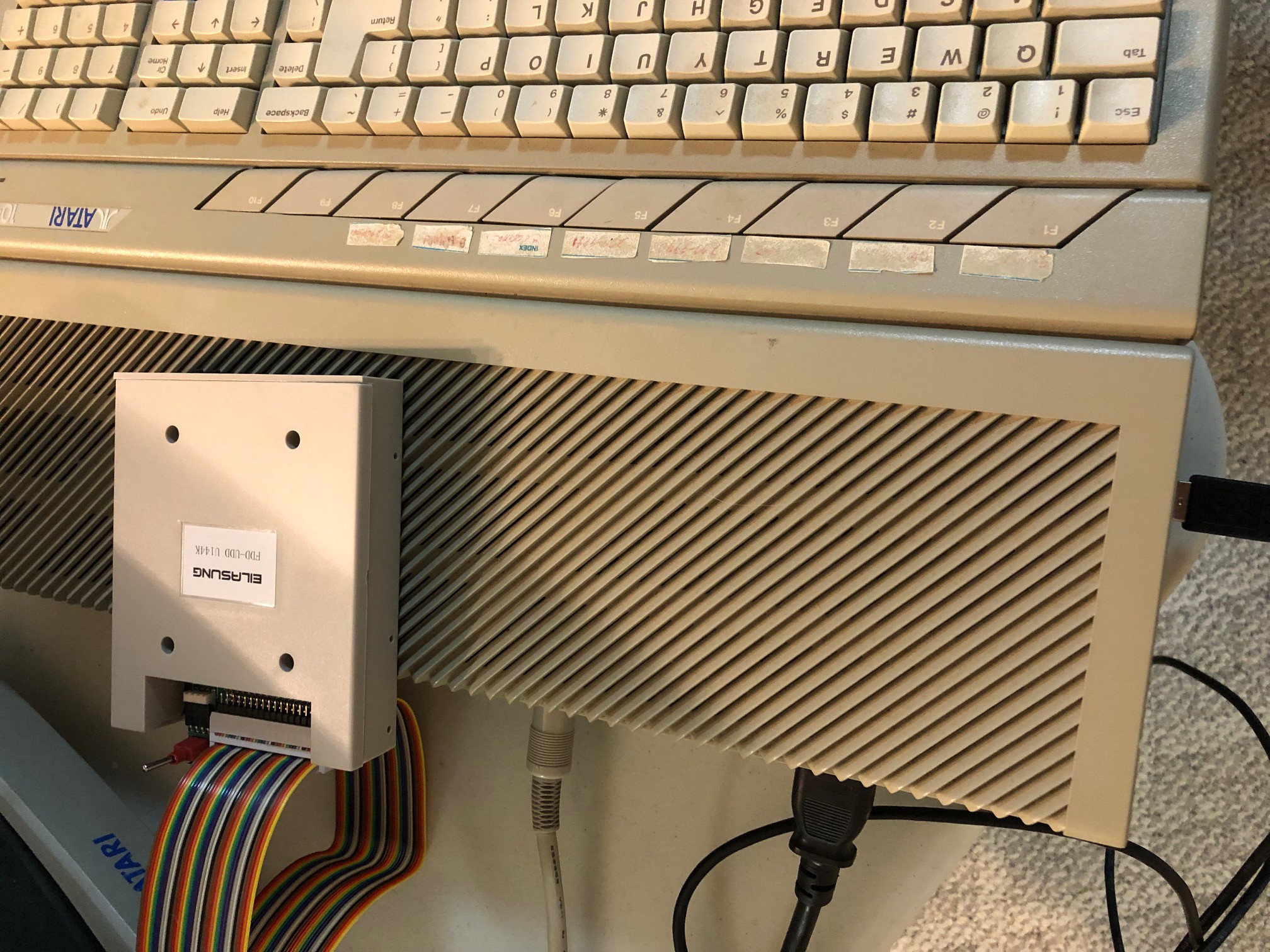
- Most Atari ST computers have a built-in floppy drive. Many users replace the internal drive with the emulated drive, but my floppy drive works fine and I'd prefer not to replace a working drive. However, there is also an external floppy connector on the back. The external drive is always drive B while the internal is always drive A. Most software requires the disk to be in drive A though. So I would prefer to have the Gotek be the external drive, but also be the A drive.
The first part of the project is getting the Gotek to work as the drive B first. Then trying to swap the logical drive letters to make Gotek drive A.
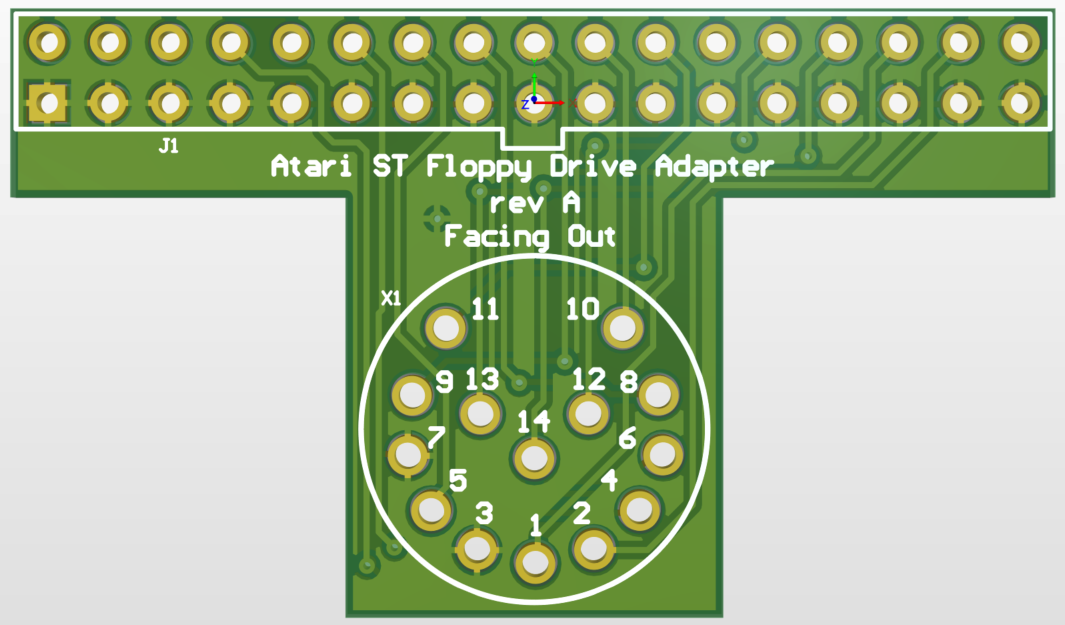
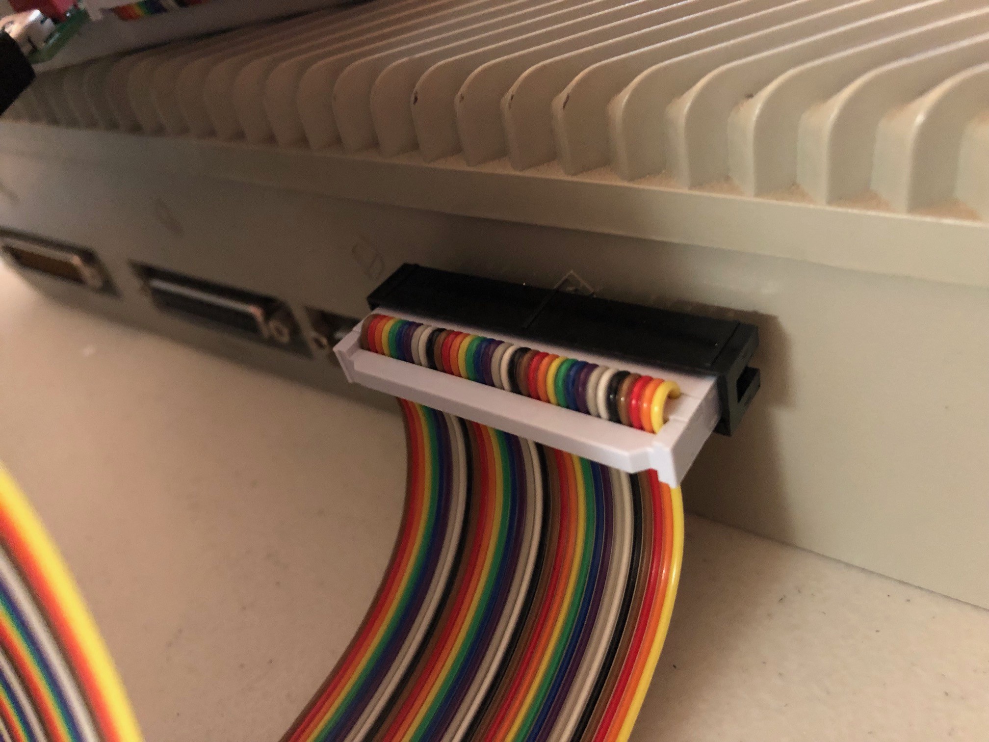
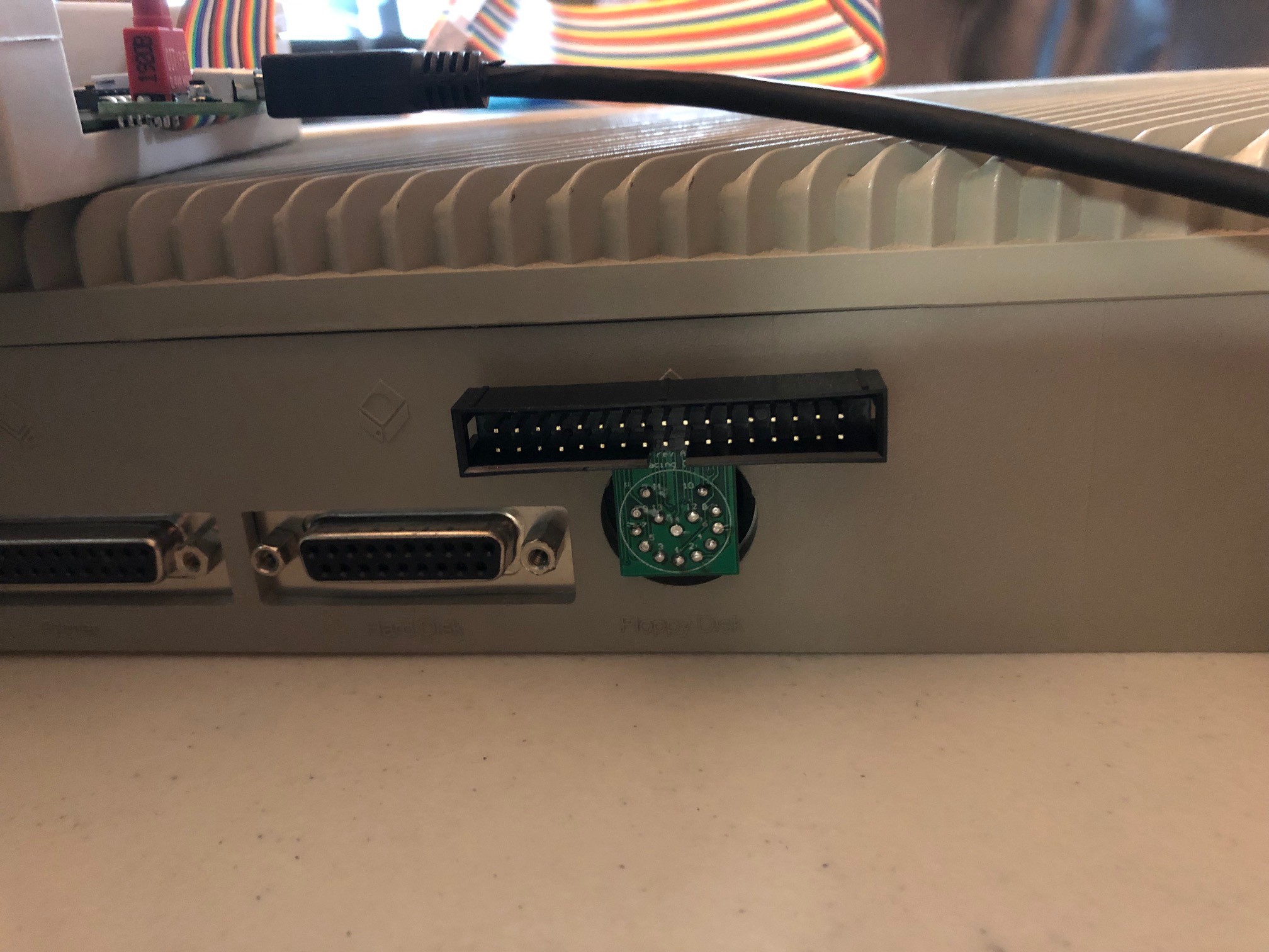
The first problem to be solved is connecting the Gotek to the Atari ST. It has a standard 34-pin, 2-row, 100mil pitch pin interface. The Atari ST has a 14-pin circular DIN which is not possible to find a cable for anymore. So I made an adapter PCB that just takes in a 34-pin header and will plug straight in to the back of the Atari ST.
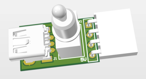
Next I need to provide power to the Gotek, and it's a standard floppy power input, but the drive only needs 5V power and not 12V power. It's possible to just use USB to provide power to it, and so I made a tiny adapter from the 4-pin, 100mil pitch floppy interface to a mini-USB connector. I also threw a switch in there in case you want to turn the drive off when the computer is off.
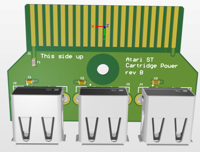
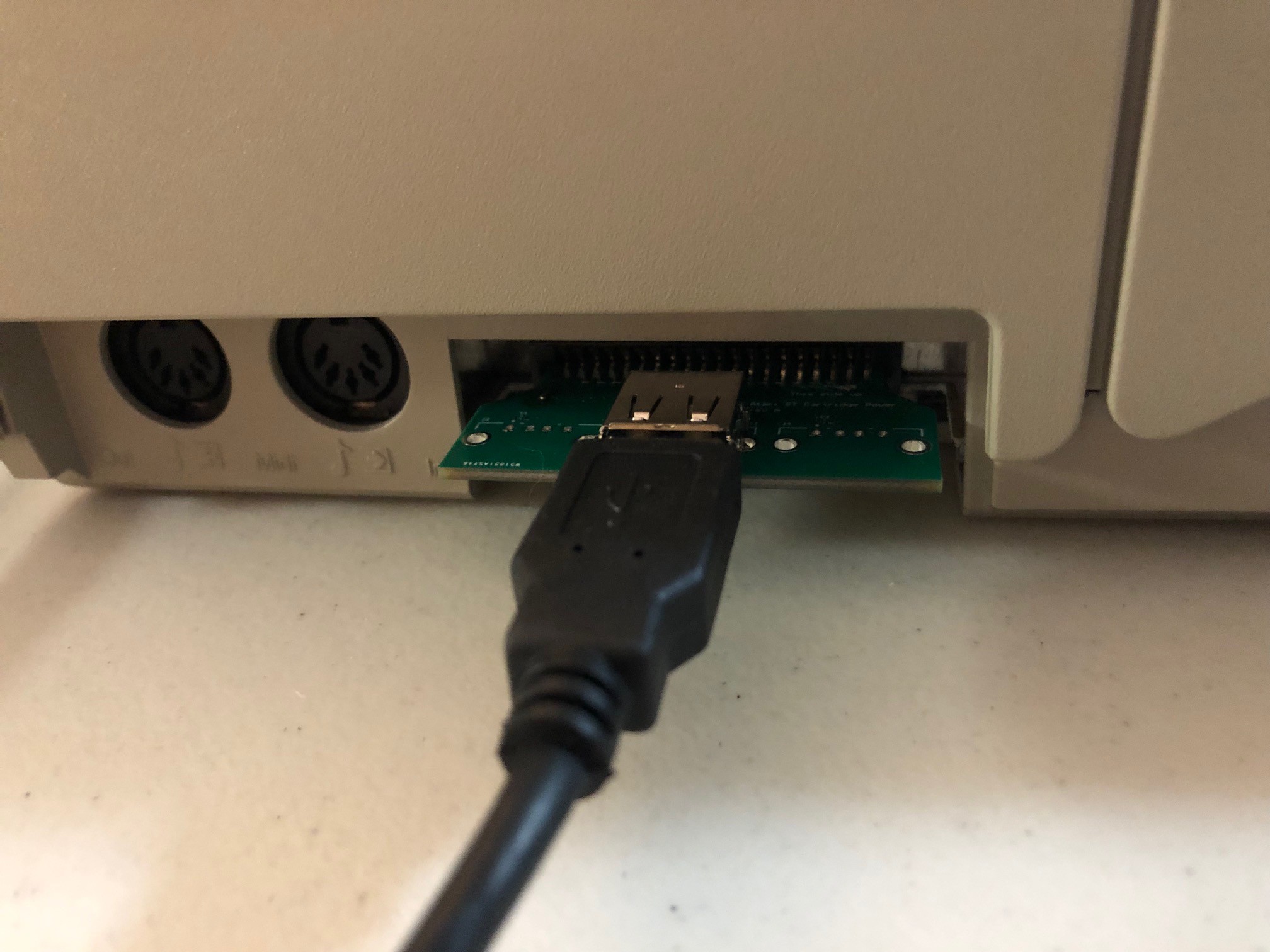
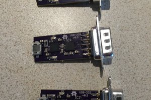
Another solution to provide power is to use the cartridge port of the Atari ST. There already exists solutions for this, but they are closed source, so I have to redesign it myself. They provide some USB type A ports which I can connect to the mini USB connector above. Then when the power to the computer turns off, the drive will turn off automatically.
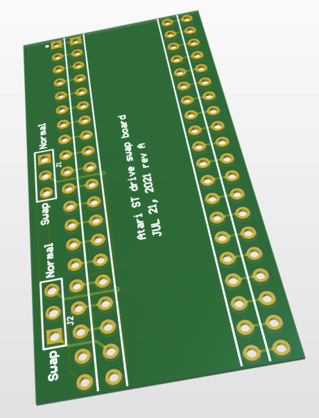
The last step is to swap the drives. This requires swapping two pins on one of the chips on the board. My plan is to desolder this chip from the board and replace it with a 40-pin socket. Then I will make a 4th PCB which has headers to go down to the socket, and then another socket going up. The chip will plug into the adapter which will plug into the socket on the board. The pins to swap will have their own headers which can be jumpered for normal operation, or drives swapped. This way, if the user wants, they can hardwire the swap, or put a jumper on some headers, or even run wires outside the Atari to a DPDT switch so it can be changed on the fly.

 Nick Sayer
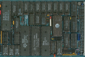
 Keith
Keith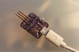
 davedarko
Are you going to make these files available (gerbers) ? Seems this project dead ended however these plans would really be helpful to so many of us if they were released.