 mihai.cuciuc
Time - it is our most precious resource. We invest some of it everytime we take a decision: to meet friends, to cook, to spend time with our loved ones, to work late, to watch a movie or to go for a run. And yet unlike our savings account it sometimes feels like the more of it we spend, the more of it we have. We MakeTime.
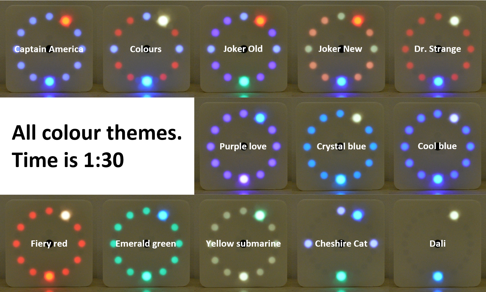
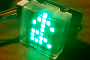
MakeTime can be simple: it shows you the time. Much like on an analog clock you read the time on a ring, with colours showing hours and minutes. Its 24 LEDs dynamically adapt to the surrounding light level, being perfectly visible in direct sunlight while staying discreet in the dark. Since it only uses 24 LEDs its resolution for showing minutes is decreased to 2.5 minutes, making it easier to read time at a glance and giving you more time to focus in a world surrounded by blinky lights competing for your attention. MakeTime is preloaded with many colour themes to make it your own.
User Interface
All interactions with MakeTime happen through the single button on the clock face. Three actions are recognized:
- click (less than 1 second)
- press (more than 1 second, less than 10 seconds)
- factory defaults (more than 10 seconds)
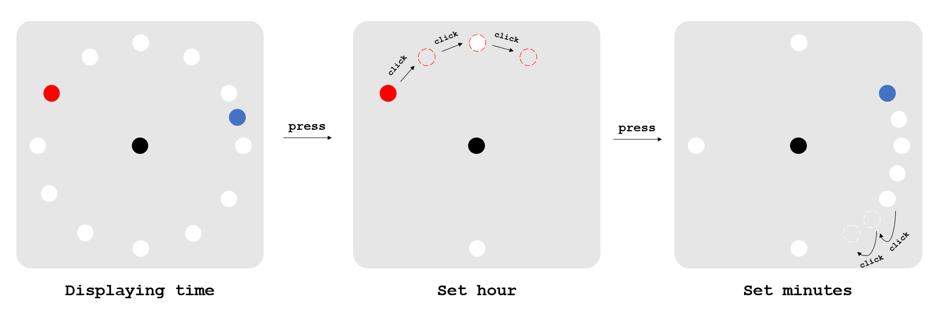
To set the time you press the button and then you can click to advance the hour. Pressing the button again allows you to set the minutes, as in the picture below. The picture shows the setting for 10:14.
Pressing the button again in the minutes menu allows you to change colour themes. All these menus have timeouts of 5 seconds during which if no action is taken you get back to the normal clock face, with your settings confirmed.
Arduino compatibility
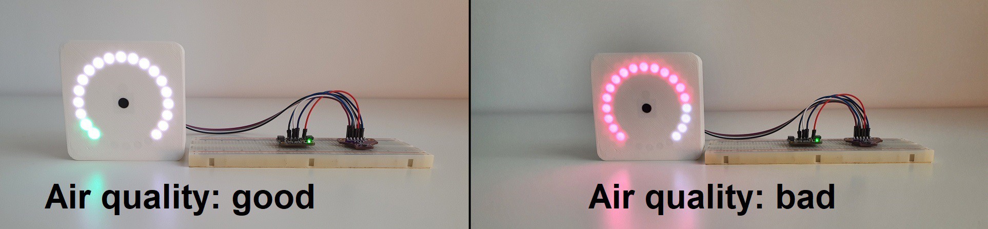
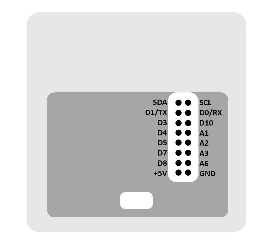
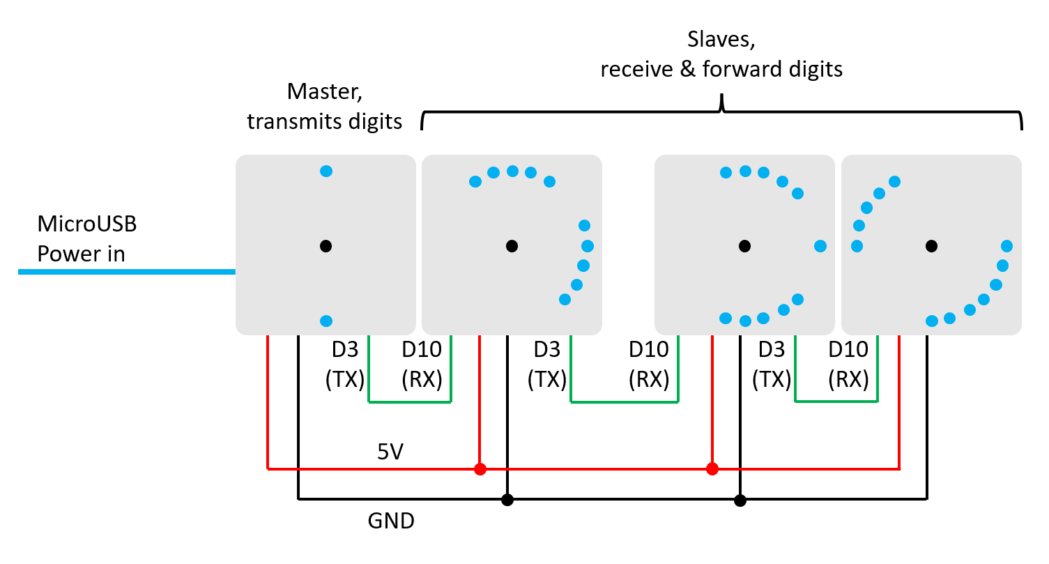
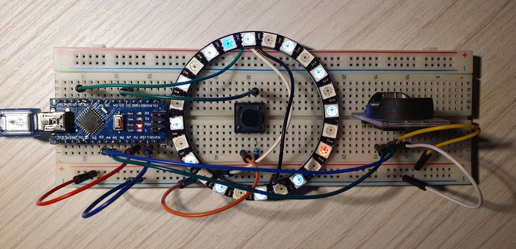
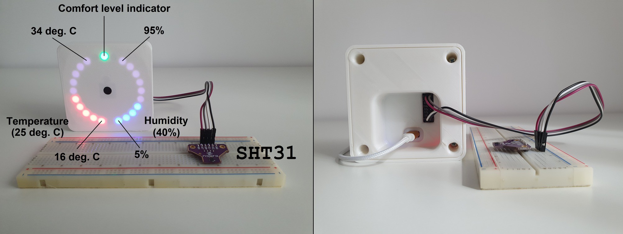
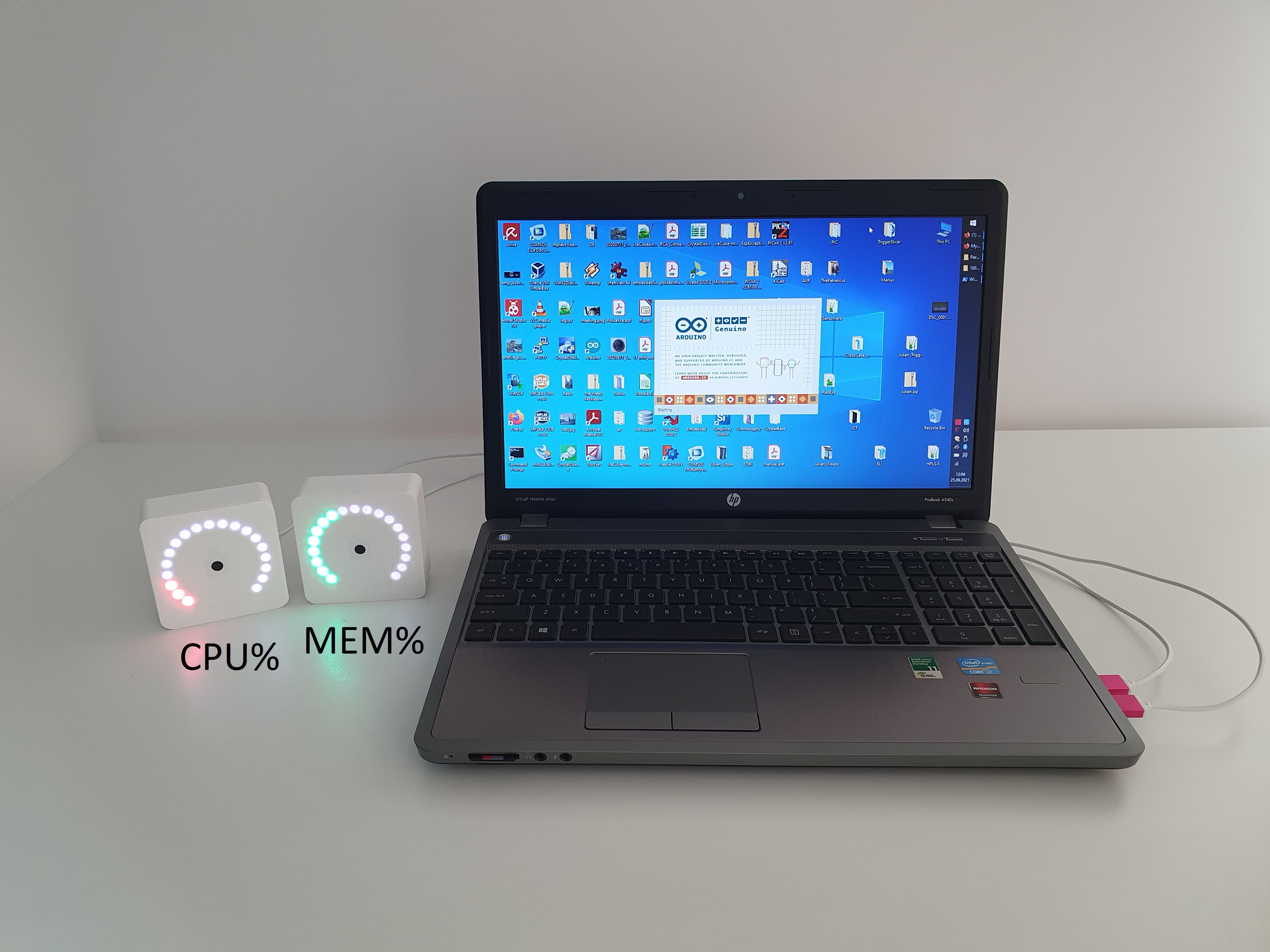
MakeTime can be complex: it is an Arduino-compatible development platform that you can hack to implement as much functionality as you need. Your freedom to hack and expand is not limited to software, though. The available schematics and the expansion header that can be populated on the PCB allows you to add sensors, communication and actuators to your heart's desire. There are two versions of the 3D model for the back, one of which provides access to the expansion header for prototyping. Project updates show different design ideas with sample code for teaching MakeTime new tricks.
You will need to program the Arduino bootloader for the ATmega328P before connecting via USB to the Arduino environment. Use the following fuse bits:
- Extended: 0xFC
- High: 0xDA
- Low: 0xFF
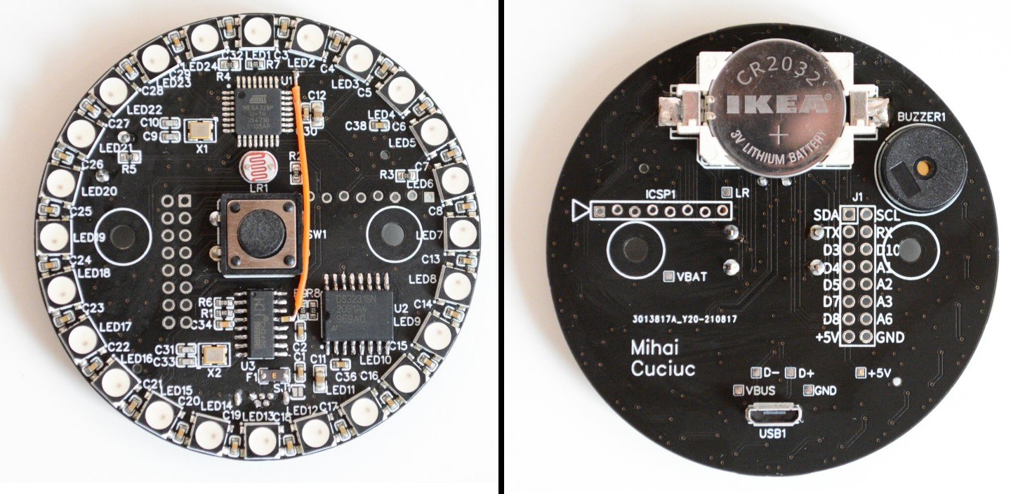
Hardware
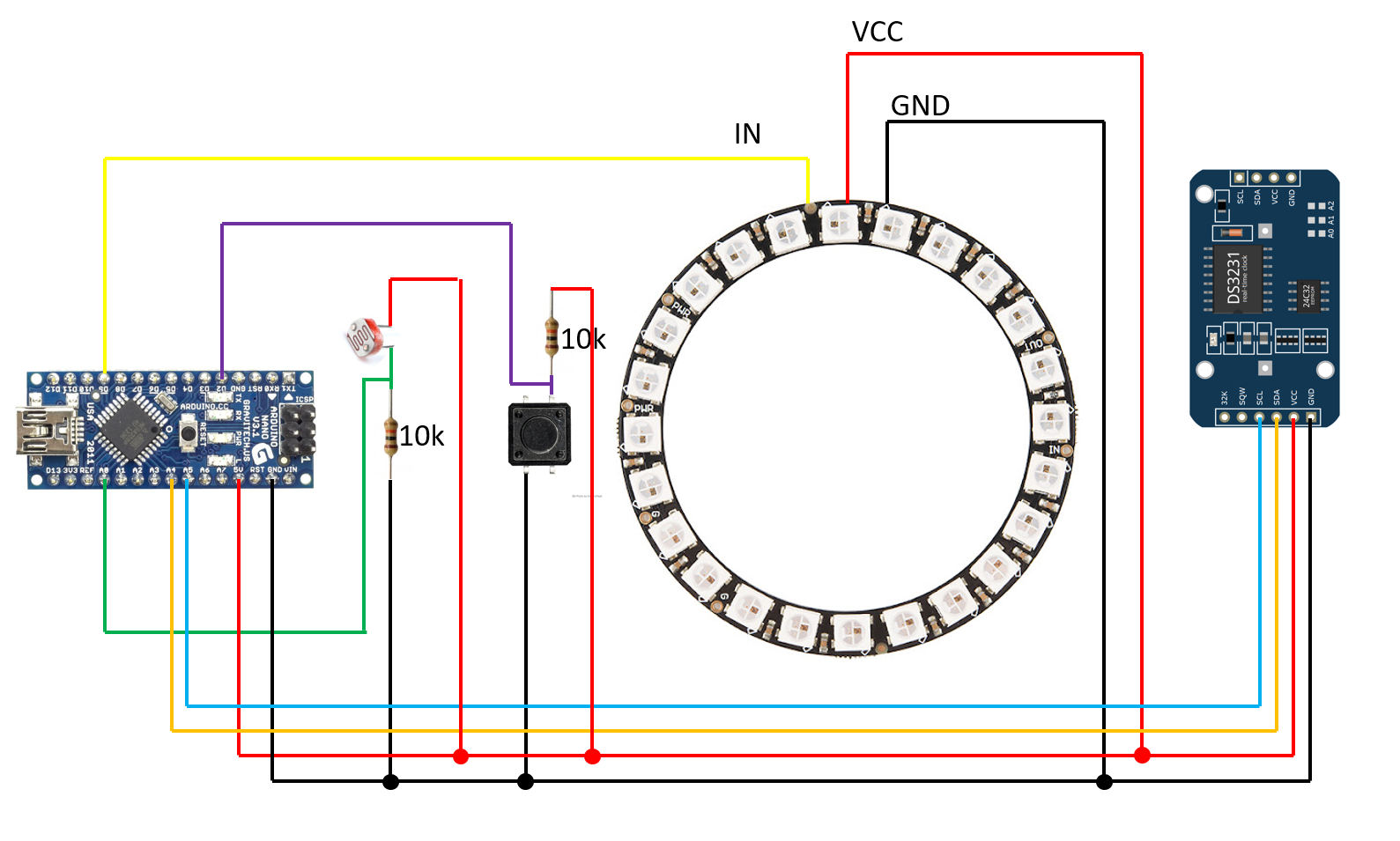
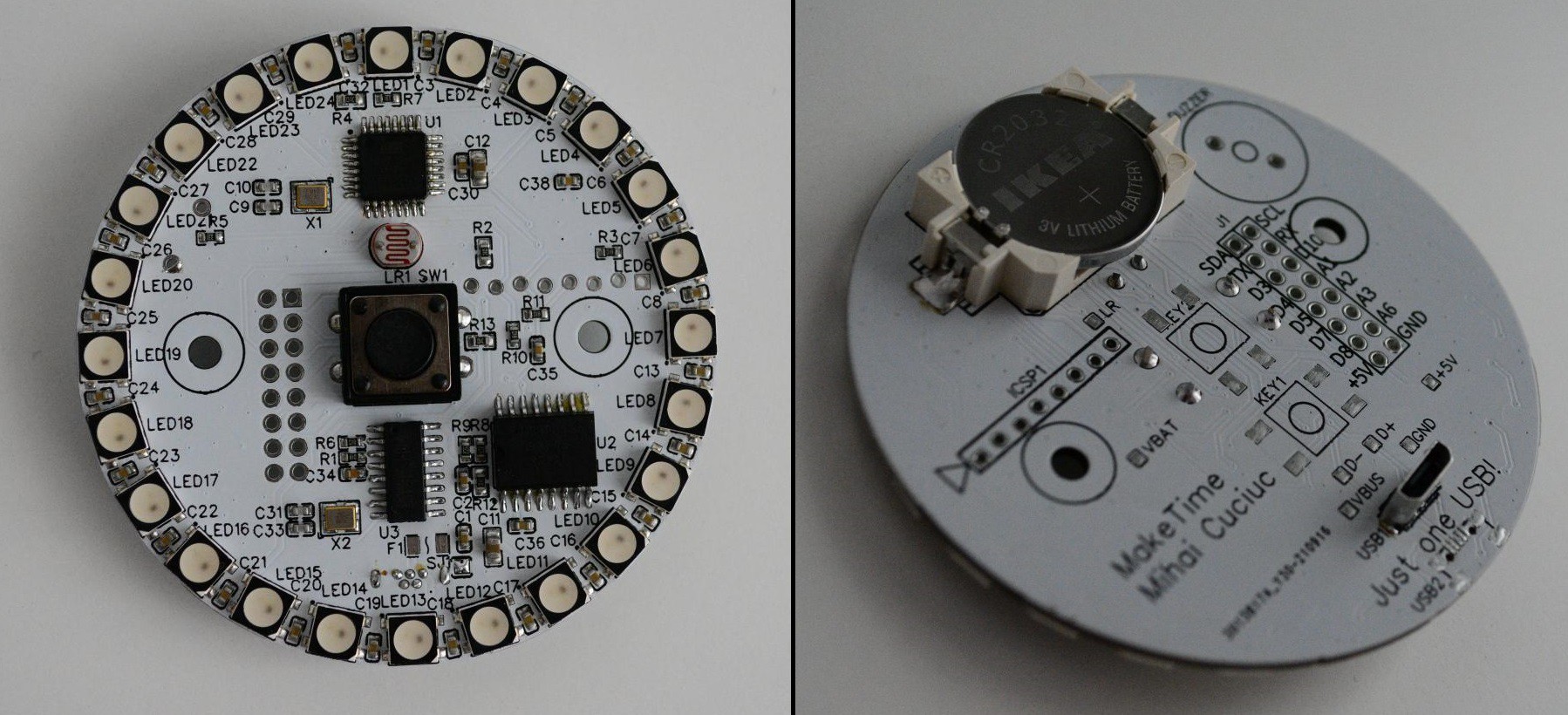
MakeTime has a custom PCB that is Arduino-compatible, i.e. it uses the ATmega328P and a CH340 USB-UART bridge. Timekeeping is done by a battery backed-up DS3231, while the time is shown using WS2812 addressable LEDs. There's also a buzzer and an LDR that allows brightness to be lowered in low-lighting conditions. The orange "blue wire" was fixed in the latest revision of the PCB.
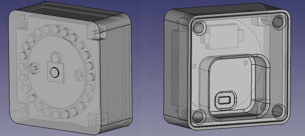
Enclosure
The case is designed in FreeCAD and can easily be 3D printed. I used 2 M3x5 screws for fixing the PCB to the case and 4 M3x8 screws for the back of the case.
Design files
The complete hardware project with schematic, PCB, BOM and all that is available on EasyEDA. Most of the components are on the front side because JLCPCB only allows assembly of components on one side. Thus you can order the PCBs there and have them mostly populated when they arrive.
PCB files, firmware and case sources can be found on Git.

 MakerM0
 Paula
Paula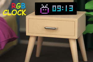
 Sagar 001