 NotBlackMagic
This update is focused on the Hardware of the Mini Cube Robot drive-train (base). All necessary mechanical parts have arrived, screws, gears, motors, wheels etc... As well as all three PCBs (Motor Encoder, Collision Sensor and Motor Drive) and the needed components to populate them.
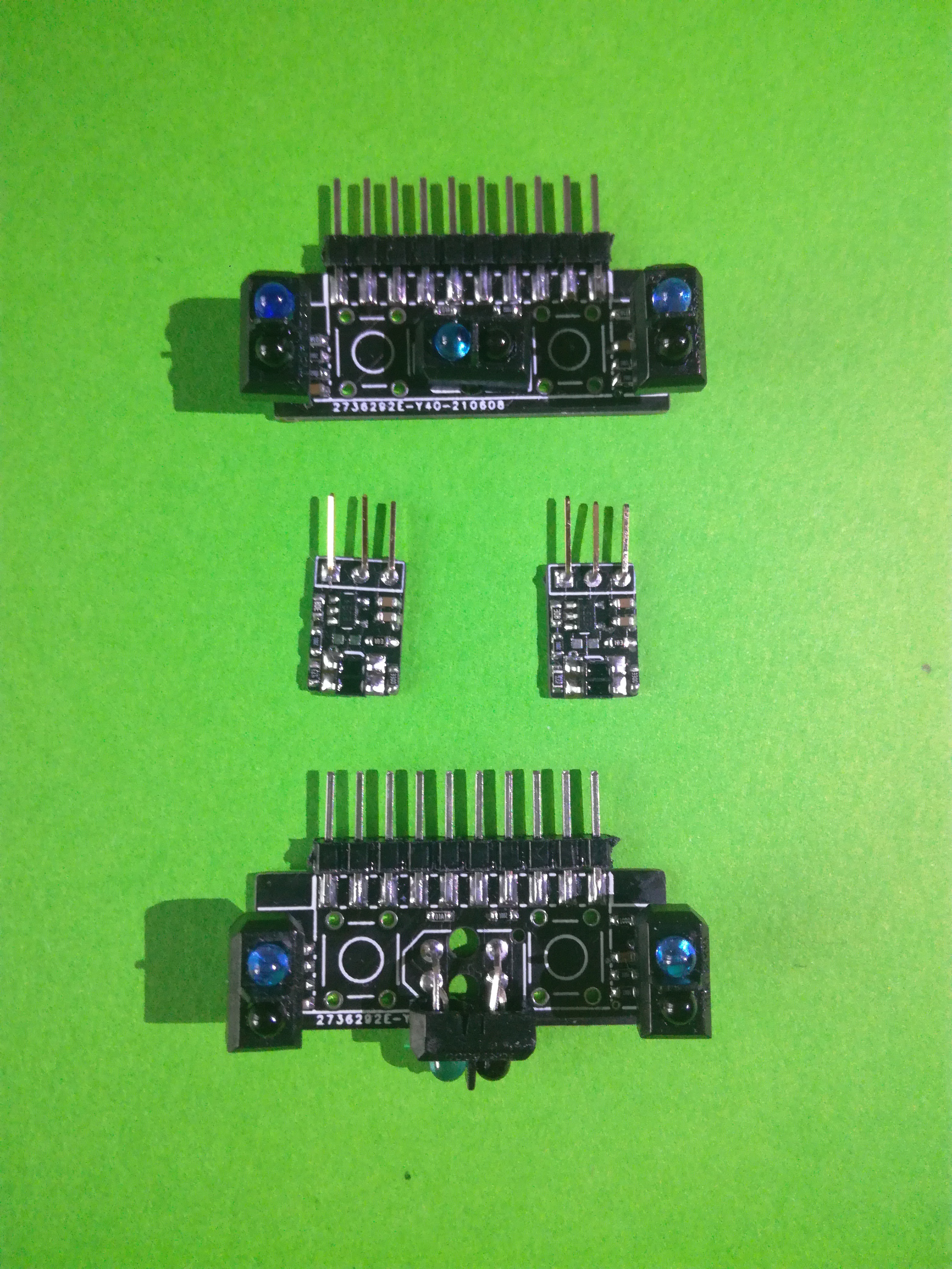
First all PCBs were assembled and tested for functionality. Both the Motor Encoder and Collision Sensor Boards (in the figure bellow) are working, all sensors are returning a good signal and are working as expected.
The Motor Drive PCB was also tested, the MCU is working as well as the Motor Drive and Battery Manager ICs. The peripherals are still being tested as well as the acquisition of all the sensors and the control of the motors.
With the PCBs functionality tested, the first Mini Cube Robot base was assembled. The mechanical parts are fitted into the bottom drivetrain holder, together with the collision sensor boards and the motor encoder boards. The latter have to be glued in place but before that they were tuned so that the voltage comparator returns a clean signal whenever the motor's plastic leave passes in-front of it (results in a future update/log). Bellow is a view of the bottom drivetrain holder fully assembled.
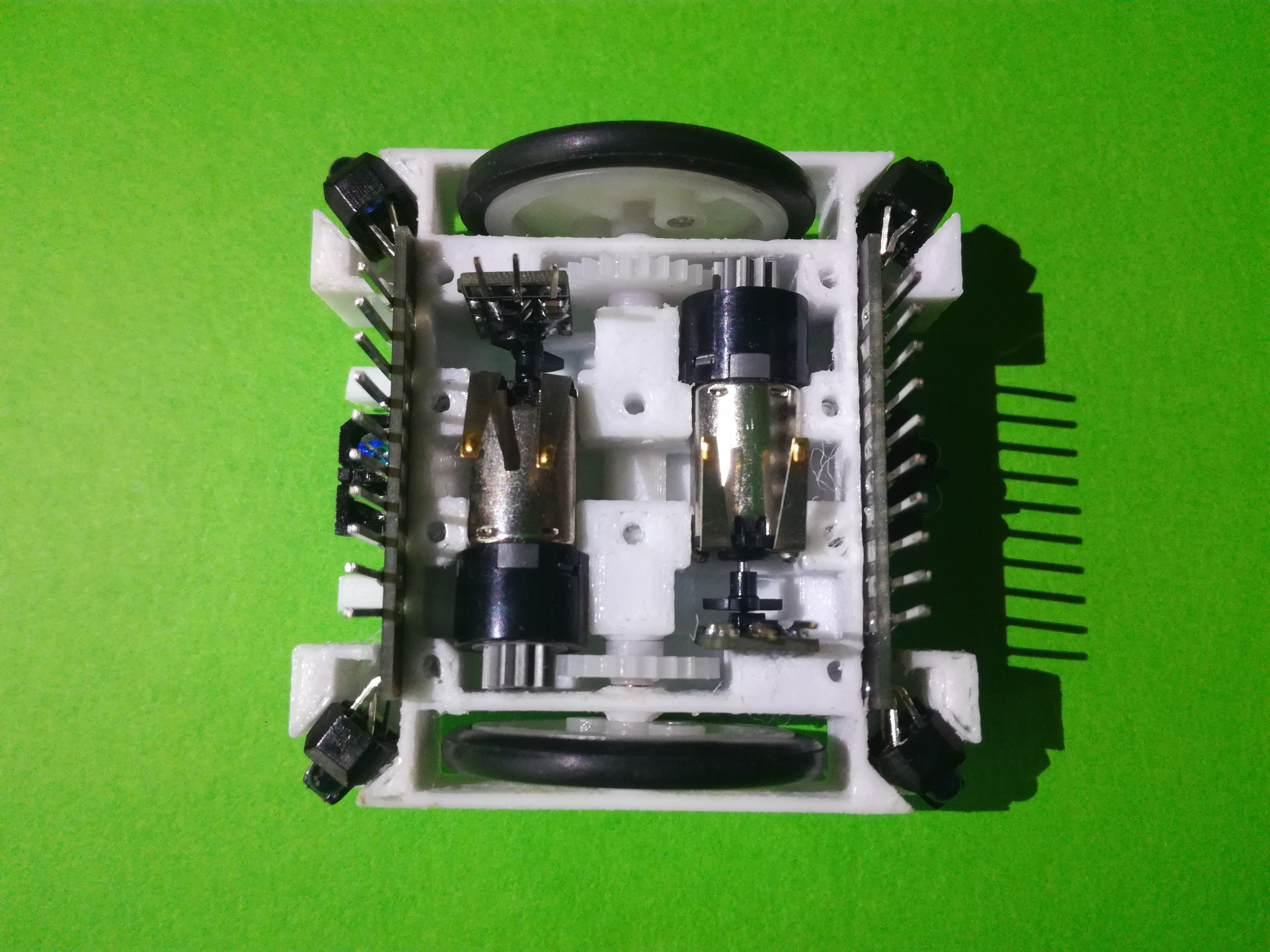
As can be seen all the parts fit very snug into there locations. The gears make good contact and the motors can spin the wheels perfectly. This is of course not the first version 3D printed, there where quite a few versions before arriving on these. The latest, the ones used here, 3D printed part files are linked to download.
With this, the top cover was added and the Motor Drive PCB was mounted on top. The collision sensor and motor encoder boards have to be soldered to the Motor Drive PCB, this is something that is planned to be changed in a future version. The assembly can be seen in the figure bellow.
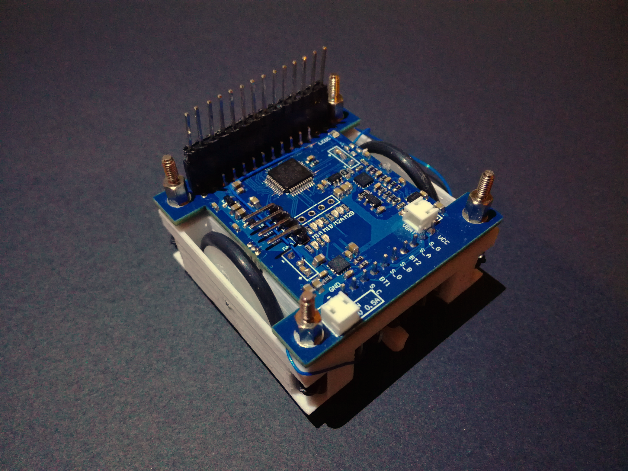
Looking at the photo there are a few blue wires visible, those connect to the motor encoder IR reflective sensor outputs to monitor if the voltage output changed with the complete assembly. Nothing major was detected and the motor encoder output continued to work as expected.
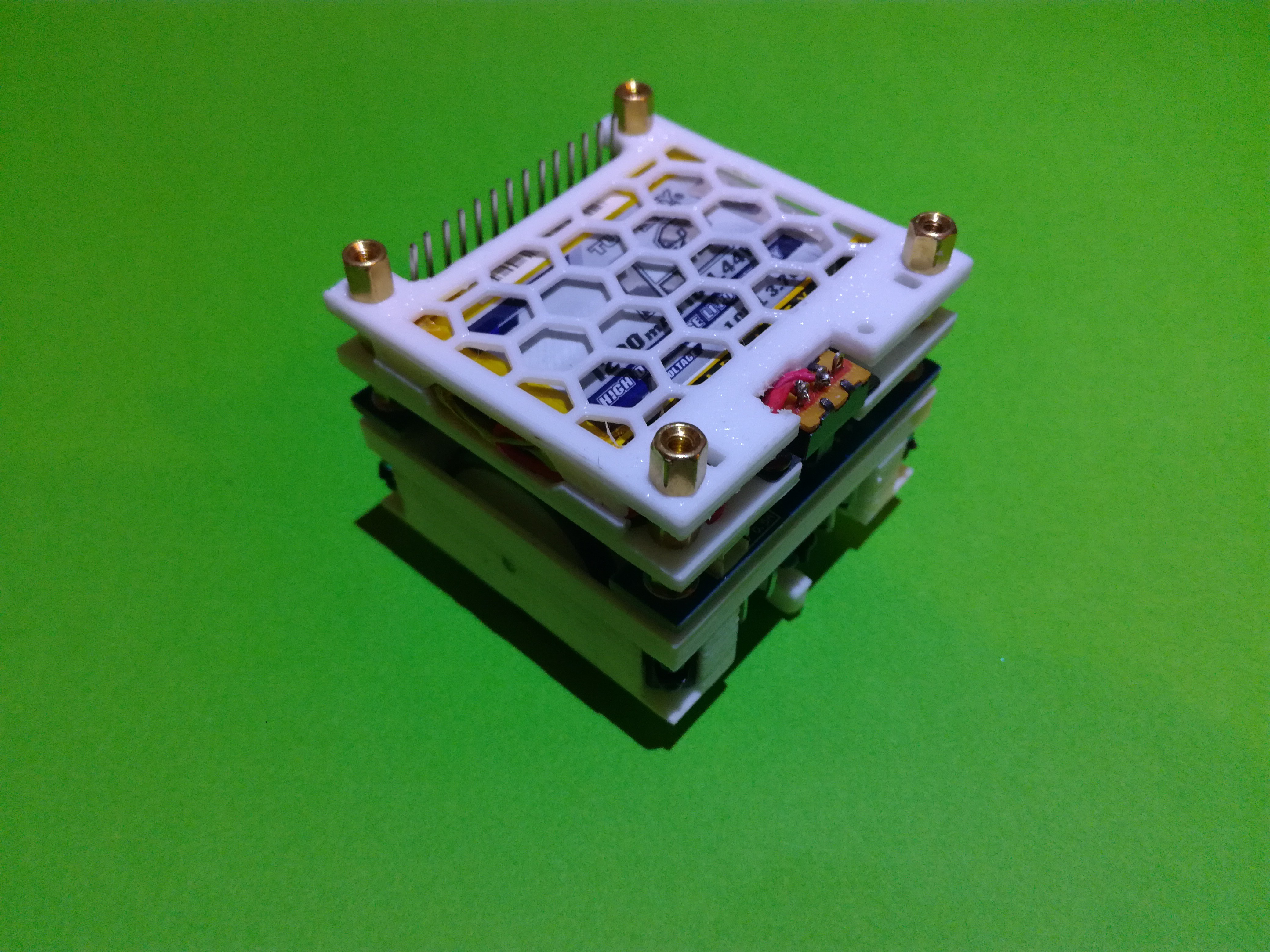
Finally the battery pack was added. It is composed of two 3D printed parts, the same part is used as the base and the top just flipped, holding a 1200mA Turnigy (HobbyKing) 1S LiPo in-between them, as well as a power switch. The fully assembled Mini Cube Robot base can be seen in the figure bellow.
This is the current state of the Mini Cube Robot project. Next is the development of the software for it, to control the motors and read all the sensors.
For some more details on each part and a first assembly guide are available on the website. The assembly instructions will be added to this project page later.
Also, updates and progress on this project, and other projects, are published on twitter.
Discussions
Become a Hackaday.io Member
Create an account to leave a comment. Already have an account? Log In.