 Electroniclovers123
Introduce a kind of LC oscillation circuit here, its oscillation amplitude can drive TTL circuit, its oscillation frequency is 1Hz.
This article will start from the working circuit and design an oscillator circuit step by step. After each step of the design, make it, and use the experience gained in the making process to carry out the next design until you successfully design and make an oscillation circuit. 1. Common emission amplifier circuit (working circuit)
The working circuit of the transistor is shown in the figure.
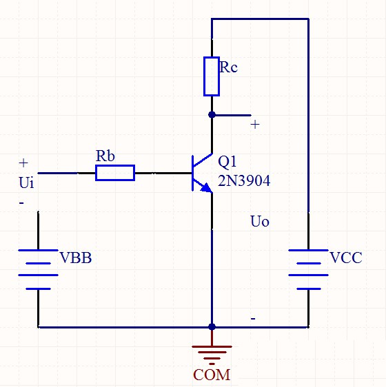
The transistor selects the transistor 2N3904. The base resistance Rb and the collector resistance Rc are used to convert voltage changes into current changes. Choose the appropriate base power supply VBB and collector power supply VCC, as well as Rb and Rc to ensure that the 2N3904 works in an amplified state.
The static characteristics of transistor 2N3904 are shown in the figure.
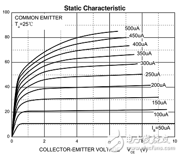
The horizontal axis is the collector-emitter voltage U_CE, and the vertical axis is the collector current I_C. The characteristic diagram is a cluster of curves.
Take a point of VCC on the horizontal axis, take a point of VCC/Rc on the vertical axis, and cluster the straight-line cut curve into multiple points. In this way, when the base current I_B changes linearly, the collector current I_C also changes linearly with the linear change of I_B within a certain interval. In this interval, it is said that there is no distortion.
In order to reduce saturation distortion and cut-off distortion, a higher power supply voltage should be selected. Here choose 6V DC power supply.
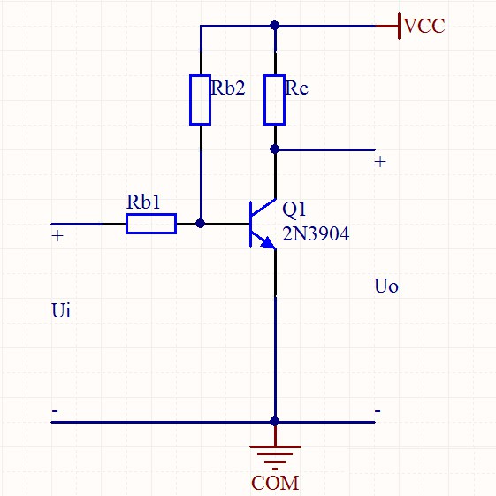
2. Direct coupling common emitter amplifier circuit
The combination of VBB and VCC of the working circuit becomes a direct coupling common-emitter amplifier circuit.
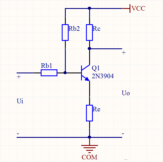
3. Operating point stabilization circuit
Add emitter resistance Re to form negative feedback to offset the temperature effect, that is, the operating point stable circuit.
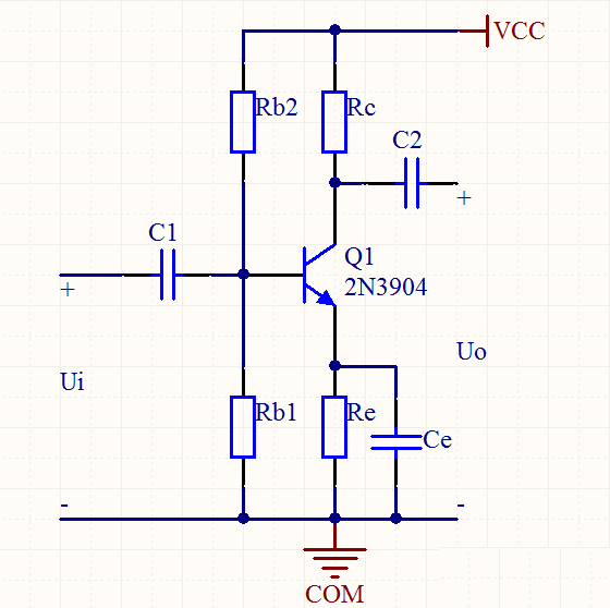
4. Capacitive coupling circuit
Add a coupling capacitor C1 and C2 between the signal source and the amplifying circuit, and the amplifying circuit and the load to become a capacitive coupling circuit. At the same time, a bypass capacitor Ce with a larger capacity should be added to bypass the AC.
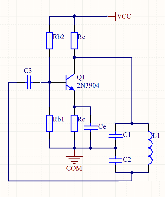
5. Capacitor feedback oscillator circuit
Connect the three ends of the two capacitors of the LC oscillating circuit to the three poles of the transistor respectively to obtain a capacitor feedback oscillating circuit. This oscillation circuit uses LC oscillation, 2N3904 amplification, and voltage series configuration feedback.
Oscillation frequency: [formula]

Adjust C1, C2 and L to adjust the oscillation frequency. Here, the 1Hz oscillation frequency is low, and larger capacitors and inductances should be selected: C1 and C2 are both 5mF, and L is 10mH.
According to the vibration condition of the oscillation circuit [formula]

Affordable vibration conditions are: [Formula]
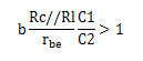
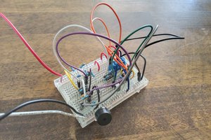
β is the magnification, r_be is the base-emitter internal resistance, and R_L is the load resistance. Use this formula to get the value of collector resistance Rc. Here Rc is 180Ω. It should be reminded: circuit production requires patience to adjust the value. However, the best value of each component is still traceable. Under normal circumstances, most components can be fixed, and only one or a few component values can be adjusted at a time. Because it needs to be adjusted all the time, it is not suitable for soldering. You can use breadboard or Tianzi circuit board.
1. Use a multimeter. It is possible to measure the current and voltage changes at various positions of the circuit during component adjustment. First, ensure that the voltage of the BE pole starts to oscillate, and then ensure that the voltage across C1 starts to oscillate.
2. Use LED light-emitting diodes. The LED must have a certain turn-on voltage, so...
Read more »

 Pavel
Pavel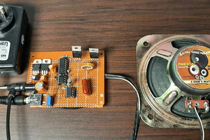
excuse me for being so frank or ignorant of the intended purpose of this project and the intent of the maker, if one calculates the circuit and components well, should the caps start pointing out on top like they do in the pictures? first thing i check for by visual inspection if a circuit works in a safe way as intended or to debug a faulty one are such visual pointers. could it be the calculations are correct just the resistance added through the breadboard and soldering caused these caps bulging out on the verge of exploding with a loud bang? what can i learn from this today, is my only reason on asking this question.