Hulk
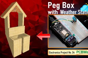
HulkIn this tutorial I am going to show you guys how to make an Arduino or NodeMCU based Weather Station using DHT11 or DHT22 temperature and humidity sensor and display it using an OLED Display.
DHT11 vs DHT22
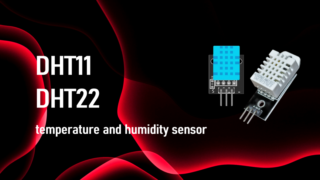
The DHT11 and DHT22 are both low-cost very basic and slow temperature and humidity sensors which can be used for basic data logging.
Despite being slower, they are very stable and consumes low power and provides relatively high measurement accuracy. The single-bus digital signal is output through a built-in ADC which is easy to read using any microcontroller. Single bus interface saves the I/O resources of any microcontroller board.
The operating voltage is between 3.3V to 5V and the sampling period for DHT11 is 1Hz or one reading every second and for DHT22 is 0.5Hz or one reading every two seconds. Hence, you can not query them more than once every second or two.

The DHT sensors are made of two parts, a capacitive humidity sensor and a Negative Temperature Coefficient or NTC temperature sensor (or thermistor).
The NTC temperature sensor is actually a variable resistor whose resistance decreases with increase in the temperature.
For measuring humidity, two electrodes with a moisture holding substrate between them is used. When the humidity changes, the conductivity of the substrate changes or in other words the resistance between these electrodes changes. This change in resistance is measured and processed and is sent to the microcontroller.
A very basic chip inside the sensor does the analog to digital conversion and spits out a digital signal which is read using a microcontroller.

Here is a comparison chart of the two sensors. Looking at this it is very clear that DHT22 outshines the DHT11 in every aspect.
However, if accuracy is your concern, and you are ready to pay a bit higher price, go for DHT22. Otherwise, DHT11 should be good enough for you.
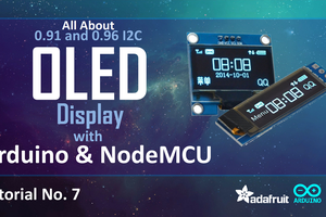
OLED Display

OLED or organic light-emitting diode is a light-emitting diode (LED) in which the emissive electroluminescent layer is a film of organic compound (millions of small LED lights) that emits light in response to an electric current.
OLEDs are used to create digital displays in devices such as television screens, computer monitors, portable systems such as mobile phones, hand-held game consoles and PDAs. An OLED display works without a backlight because it emits visible light.
There are many types of OLED displays available in the market based on their:
- Sizes
- Color
- Brands
- Protocol
- SPI (Serial Peripheral Interface) or I2C
- Passive-matrix (PMOLED) or active-matrix (AMOLED) control scheme
To know more about OLED Display and to know how to connect multiple OLED Displays using TCA9548 multiplexer check out my tutorial number 7
OLED Display with Arduino and NodeMCU link is in the description below: https://www.youtube.com/watch?v=_e_0HJY0uIo
Lets have a closer at these two displays.
At the back of these displays there are heaps of SMD capacitors and resistors soldered on-board; but, since its an I2C device we only care about these 2 pins (SCL and SDA)
The display connects to Arduino using only four wires – two for power (VCC and GND) and two for data (serial clock SCL and serial data SDA), making the wiring very simple. The data connection is I2C (I²C, IIC or Inter-Integrated Circuit) and this interface is also called TWI (Two Wire Interface).
The on-board pins can be in different order, so always triple check before hooking it up to your project.
Operating voltage is between 3v to 5v but, it is best to use the guidance from the manufacturer's datasheet.
Sometimes we need to use 2 displays in our projects. So, how can we achieve this?
The trick is to have a configurable address on your display. This unit has a configurable address between 0x78 and 0x7A. Just by unsoldering the 0Ohm resistor from one side and hoking it up to the other side or just by putting a global solder we can change the address.
In picture these displays look very...
 Lithium ION