General overview
With the robot arm fully extended vertically, which is its home pose, its bounding dimensions are approximately 250 mm width, 280 mm depth, 700 mm height. Its estimated mass from the CAD is around 6.5 kg. When fully extended horizontally, its reach is approximately 500 mm. The arm has been tested with a max payload of 0.5 kg. While it was able to pick and place a payload of this mass at near full arm extension, the joint 3 stepper driver was damaged during payload tests of 0.5 kg. Therefore, further testing and possibly mods are needed to ensure a max 0.5 kg payload capability. The robot arm was designed in Fusion 360, and the CAD files (Fusion 360 and STEP format) are available at the following links:
https://github.com/jk87/Open6X/tree/main/CAD/rev1
https://github.com/jk87/Open6X/tree/main/SOFTWARE/rev1
(BoM document to come)
(Wiring diagram to come)
Below are some videos showing an overview of the robot arm together with routines of joints homing, joints sweep and payload pick-and-place.
Mechanical design
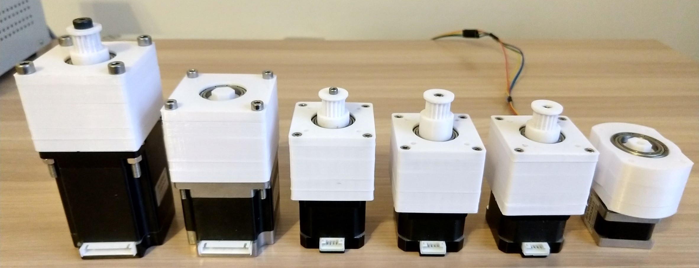
The initial release of this robot arm used stepper motors to directly drive toothed belts at the joints. In this first revision, 3D printed
planetary spur-gear reducers (see image above) have been added to all joints to increase joint torque output. Additionally, all the toothed drive belts are now
HTD-3M, and all pulleys and idlers are 3D printed. The following
table summarises the robot arm's links and actuators.
| Joint |
Driven link |
Motor |
Motor holding torque |
Planetary gear reduction |
Belt drive reduction |
Total reduction |
|
1 |
Shoulder |
Nema 17-40 |
0.4 |
4.5 |
6 |
27 |
|
2 |
Upper arm |
Nema 23-76 |
1.9 |
4 |
5 |
20 |
|
3 |
Elbow |
Nema 23-57 |
1.3 |
4 |
5 |
20 |
|
4 |
Lower arm |
Nema 17-34 |
0.13 |
4.5 |
4 |
18 |
|
5 |
Wrist |
Nema 17-34 |
0.28 |
4.5 |
4 |
18 |
|
6 |
Gripper |
Nema 14-28 |
0.28 |
5 |
n/a |
5 |
|
7 |
Gripper fingers |
MG996R |
0.15 |
n/a |
n/a |
0 |
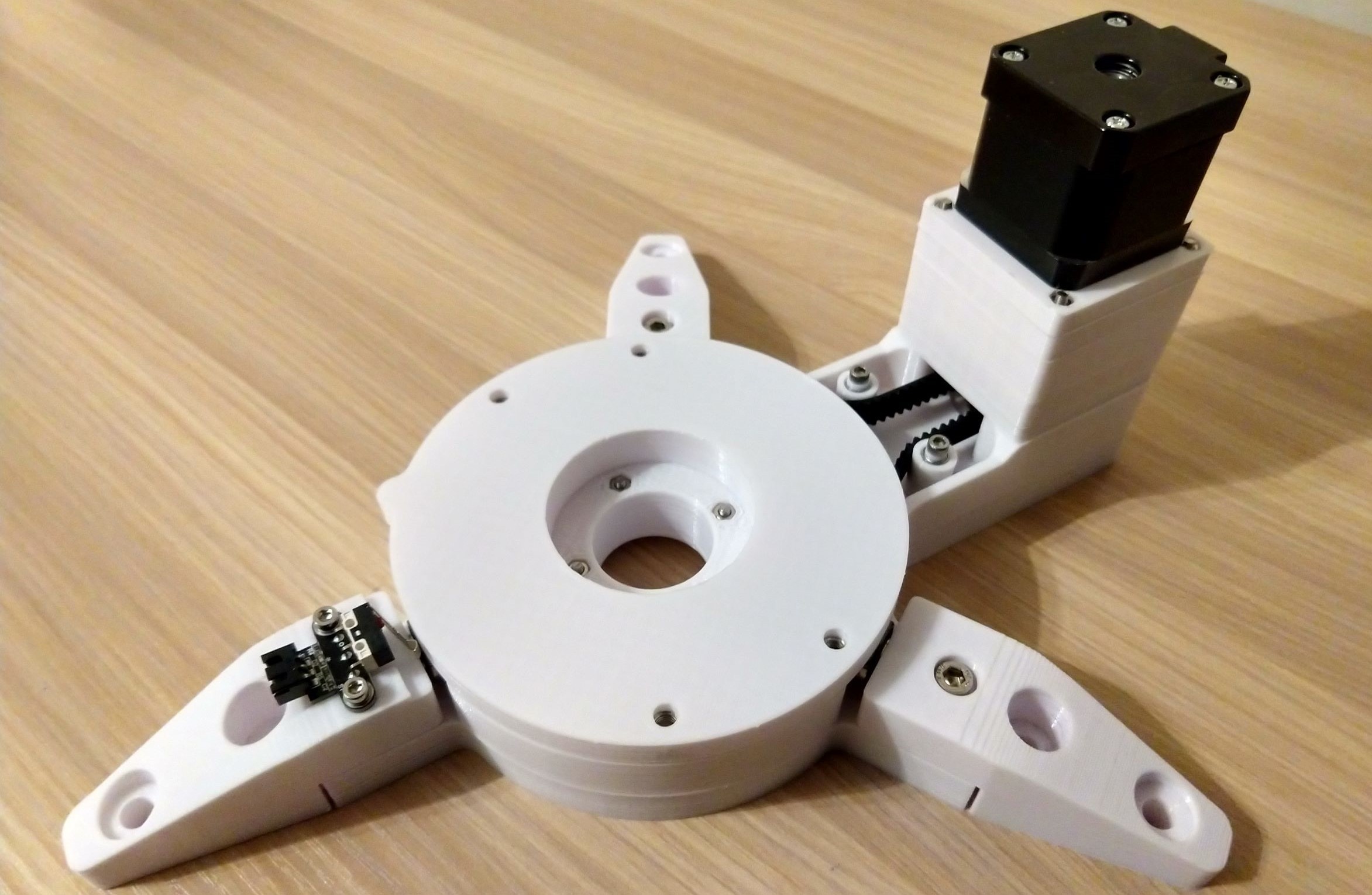
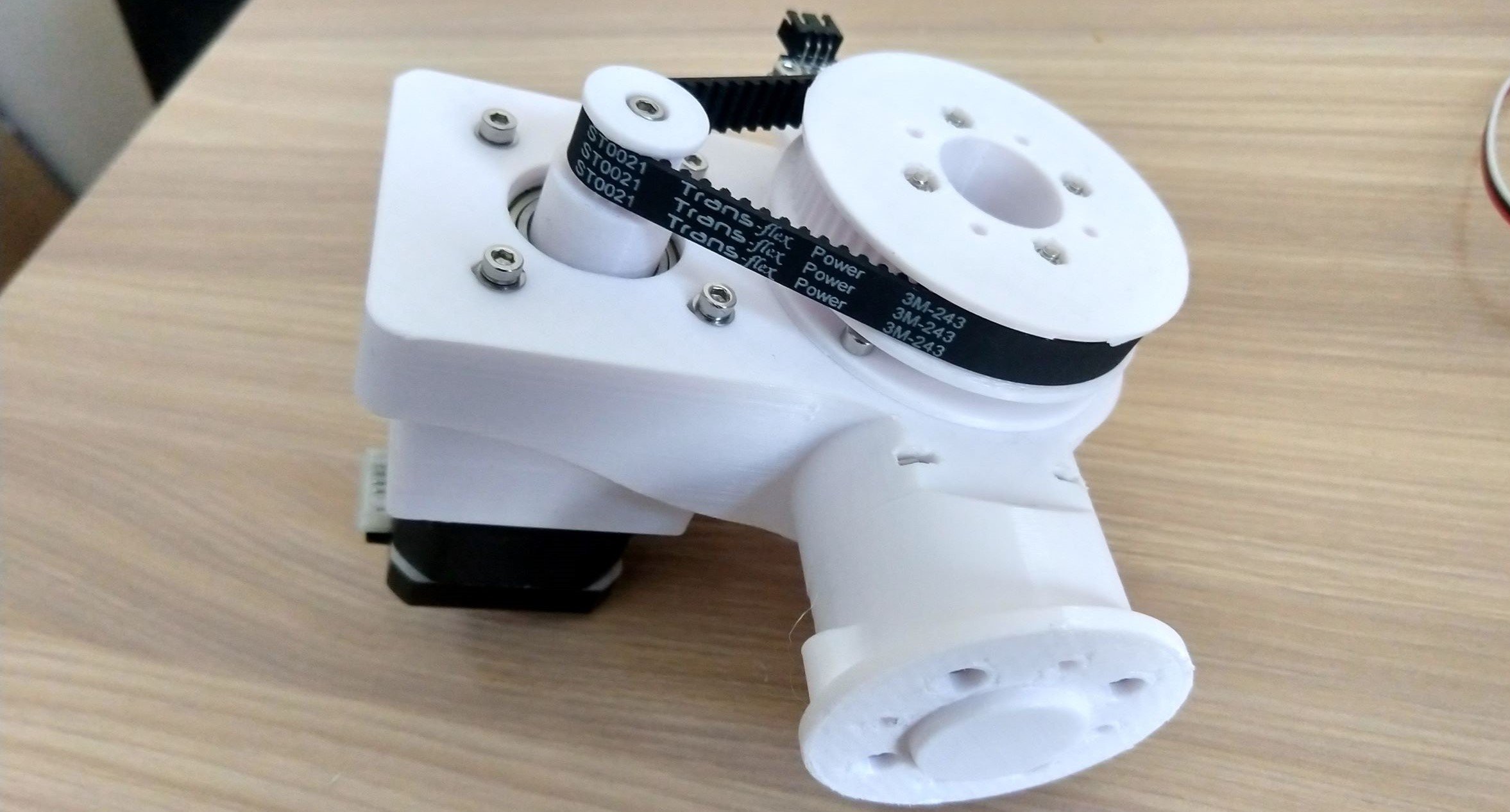
At
the base link (see image above), a Nema 17-40 stepper with a planetary gear reducer actuates a belt driving a pulley fixed to the bottom of the shoulder link (joint
1), adding a further speed reduction. The radial load at the belt driven pulley is taken by a radial
bearing secured to the base link. The axial load of the shoulder link
is taken by three small bearings fixed to the base link, on which the
shoulder link rolls as it rotates. Extending outward from
the base link are three feet to provide additional stability, and
which are also used to secure the robot arm to a stationary base
(I use a wooden board clamped to a desk). At the robot arm joints, toothed
belts are generally tensioned using 3D printed idlers rotating on bearings, and
radial bearings are used to take the load at the joints (mostly radial loads, joints 4 and 6 also have small axial loads) .
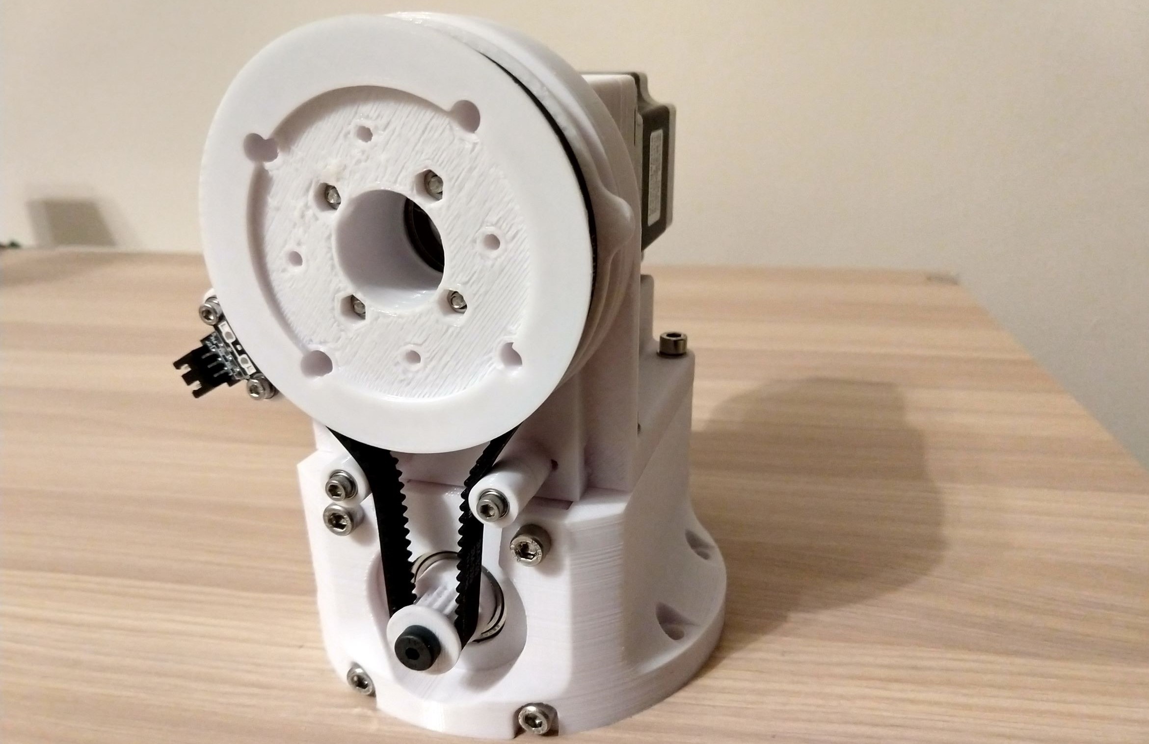
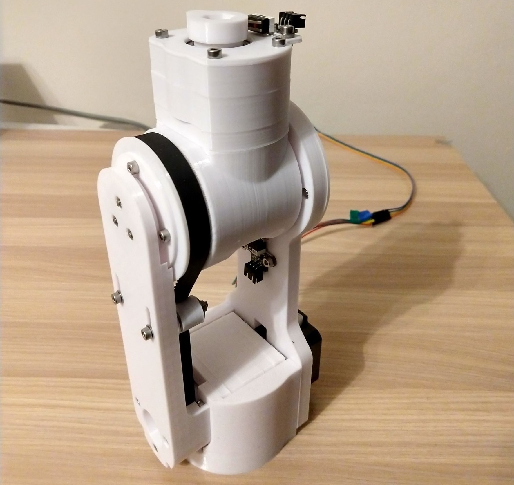
The shoulder link (see image above) holds the two Nema 23 steppers, each fixed to its own bracket, one placed on top of the other. The lower stepper (Nema 23-76) with a planetary gear reducer actuates a belt driving a pulley fixed to the upper arm link (joint 2), adding further speed reduction. Passing through the axis of that driven pulley is a 3D printed shaft coupling the upper stepper (Nema 23-57, with its planetary gear reducer) to a drive pulley fixed to the upper arm link. Shoulder screws are used at the Nema 23 drive pulleys to support the high radial loads at the drive belts.
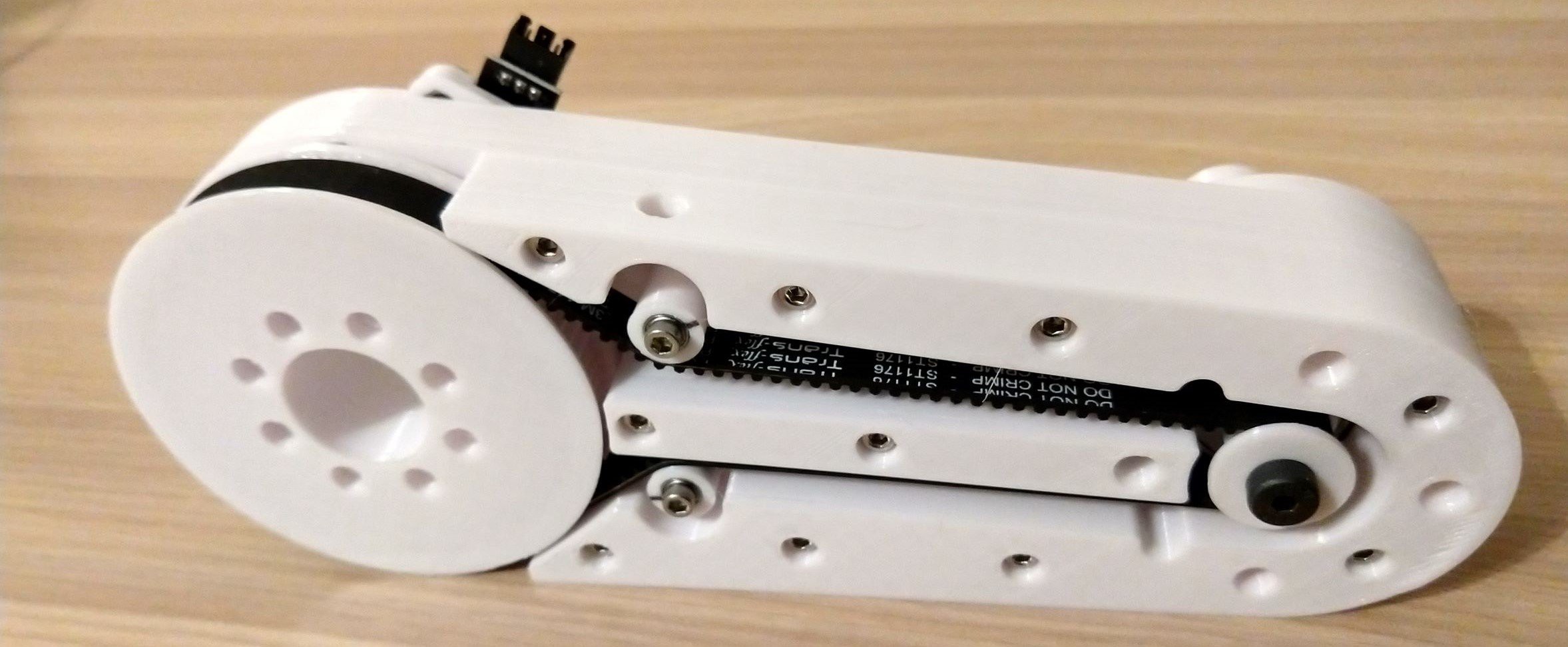
A belt extends across the upper arm link (see image above) between the drive pulley coupled to the Nema 23-57 stepper at the shoulder link, and a driven pulley fixed to the elbow link (joint 3, see image below). Attached to the elbow link is a Nema 17-34 stepper with a planetary gear reducer that actuates a belt driving a pulley fixed to the lower arm link (joint 4). No idlers are used to tension the belt at this joint. Instead, the belt is tensioned by pulling the stepper away from the driven pulley along slots at the stepper fixing screws.
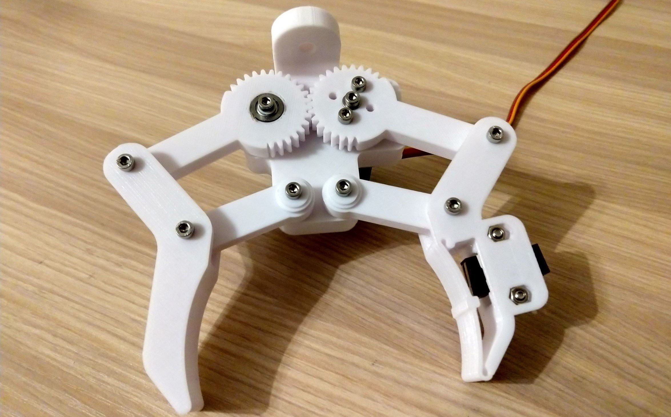
A second Nema 17-34 stepper with a planetary gear reducer is attached to the lower arm link (see image above), actuates a belt driving a pulley integrated into the wrist link structure (joint 5). The lower arm link supports the wrist link, in which a Nema 14-28 stepper is attached. The Nema 14-28 stepper with a planetary gear reducer drives the gripper link (joint 6, see image below). An MG996R servo drives the gripper fingers, which have a maximum open finger separation of 80 mm. One of the gripper fingers is seen to have a limit switch attached to it. This is for on-going development looking to use the deflection of a beam flexure to activate the limit switch when a payload is suitably grasped.
Electronics
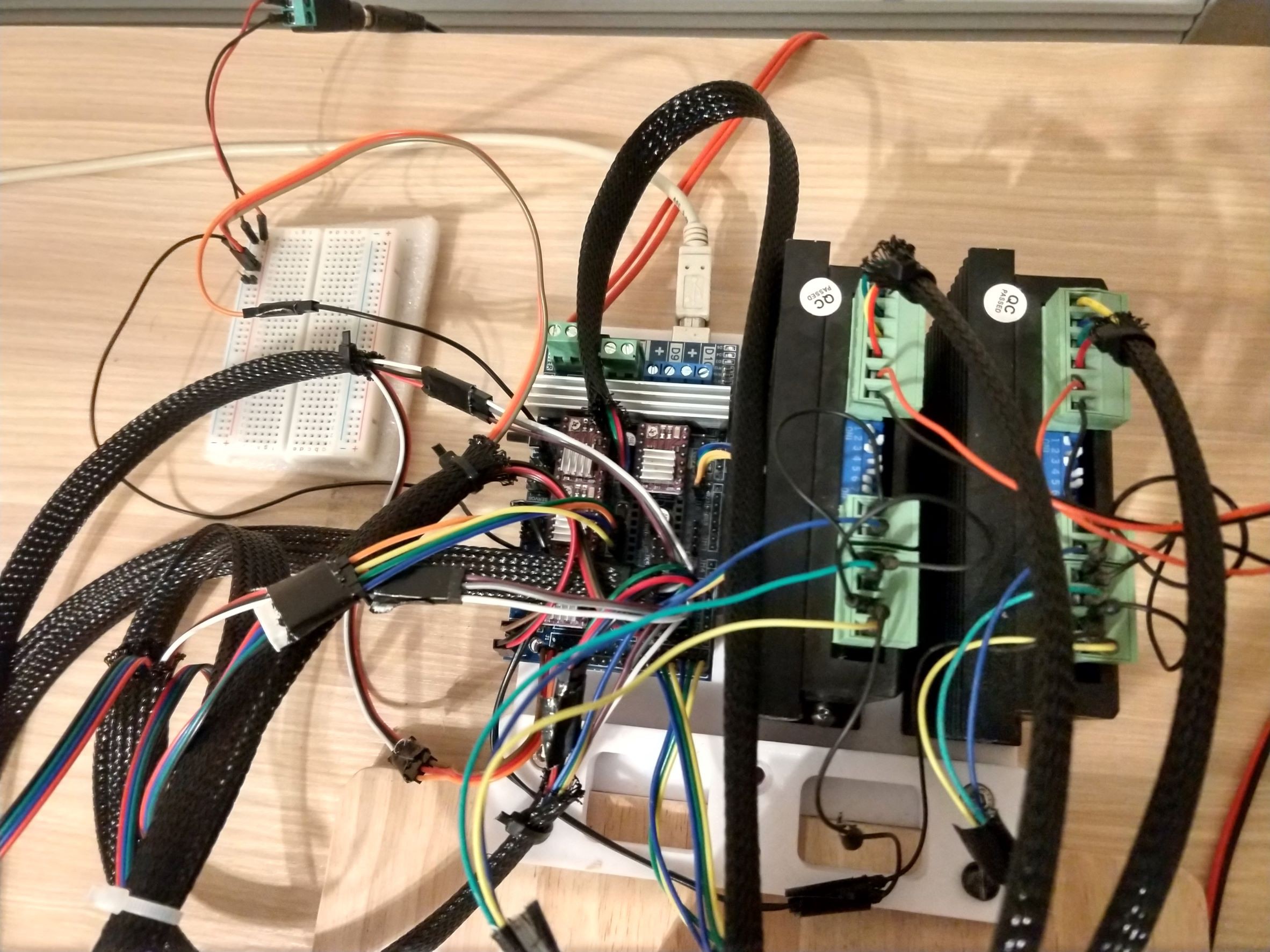
Four DRV8825 stepper drivers installed on the RAMPS 1.6 shield connect to the three Nema 17 steppers and the Nema 14 stepper. Two DM556 stepper drivers connect to the two Nema 23 steppers. The Nema 23 and 17 steppers are controlled in half-step mode, and a 1/8th microstep setting used for the Nema 14 stepper. The DM556 drivers are powered at 24V using a 30V, 10A power supply, while the RAMPS shield is powered using a 12V, 15A power supply. The MG996R servo is powered using a 5V, 2A power supply. A push button attached to interrupt pins on the Arduino via the RAMPS shield is used as an emergency stop, where when activated, the robot arm control routine is halted in the Arduino software. However, the emergency stop function is not currently implemented during the robot arm homing routing.
I’m yet to produce a wiring diagram for the electronics. In the meantime, looking at the main file of the Arduino code where the Arduino MEGA pin constants are defined will likely get you roughly halfway there. I’ve added comments in the code describing the Arduino MEGA pin designations for the actuators and sensors I’m using, and links to the online files I used to understand the mapping of the RAMPS 1.6 shield headers to the Arduino MEGA pins.
Software
Arduino code is used to control the robot arm, with the Arduino serial monitor providing the user interface. The user interface is very minimal, using text commands over serial, and requires one to build familiarity with the fixed frame (global reference) and the moving end-effector frame at the gripper fingers that is actuated to manipulate the payload. This is not a long term solution, and the plan is to develop a more user-friendly interface over the coming months. The key functionality in the Arduino code are:
- homing routine using the joint limit switches
- returning the joints to their home positions without using the limit switches
- running forward kinematics to move the joints to predefined setpoints and display the end-effector position and orientation
- running inverse kinematics to calculate joint setpoints that will position the end-effector at a target position and orientation
- cycling through predefined waypoints to execute a series of trajectory motions, where the joint positions corresponding to the desired end-effector position and orientation at the waypoints are defined in the Arduino code
There are also some additional functionality such as enabling and disabling the steppers, sequentially sweeping the joints across their predefined limit range, displaying the current state of the robot arm (joint positions and end-effector position and orientation) and manual control of the gripper fingers using a potentiometer (or similar input sensor) which may be useful while the robot arm is under development.
The software currently has many limitations, with the main one likely being insufficient implementation of safety checks to ensure safe operation of the robot arm. The software currently only checks that the joint setpoints do not exceed their predefined limits before running the motors to execute a trajectory motion. No checks are made to ensure the robot arm links don’t run into each other, or into any objects, persons, etc, within its working envelope. This is currently up to the user to ensure, and so, care should be taken when operating the robot arm.
Next steps
Listed below are the key issues and improvements I'm looking to make to the robot arm in the near future to improve it's functionality and user experience.
-
Troubleshooting failure of the joint 3 stepper driver
-
Retrofitting encoders at the output of each joint to enable closed loop control
-
Developing a better user interface to control the robot arm