 Maximiliano Rojas
Hi guys, in this log I intend to explain a little bit how the mobile platform works, so as usual this subsystem will be divided into two main topics: hardware and software, but before that lets see a video!
Software
One of the main concepts in the whole process of this robot design is modularity, for this reason, I think ROS is a good choice, with this meta operative system you can easily create programs and interconnect them, basically, it establishes a solid way to create complex robotic systems with not only a high degree of personalization but also its wiki provides a large amount of documentation and ready-to-go packages of programs, a good characteristic to fastenest the prototype development process, of course, ROS by itself can be very confusing and tangled when the projects become big enough and that's why I decided to use docker with it, containers allow me to separate the software in different groups that can communicate between them (a nice trick is to configure them to connect to the host network so no multimachine ROS parameters assignment are necessary), in the light orange square of the Figure 1 you can see the general and simplified structure of the docker-ROS:
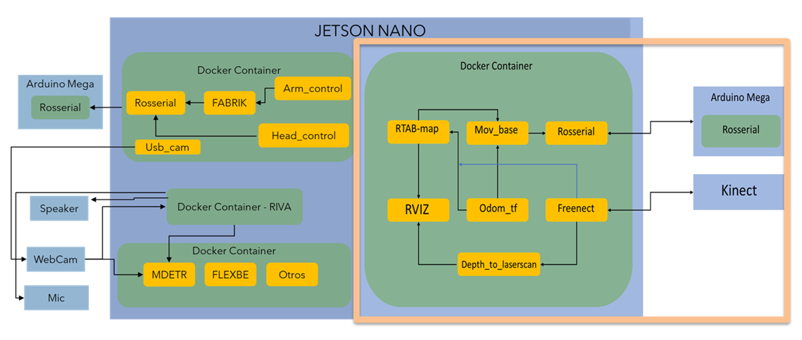
Let's briefly summarise what all the navigation nodes do and how they work together:
- Rosserial: This a ROS package provided for the community that allows the computer to communicate easily with some microcontrollers development boards such as Arduino and Esp8226, the microcontroller can be a node with a very similar structure with a c++ one, and there are enough messages types to prototype[1].
- Freenect: This is another ROS package that provides all the necessary files to connect a PC with a Kinect V1, when is launched it provides several topics with RGB, cloud point, registered point cloud, and tilt control messages (between others) basically with this I can obtain the necessary data to create the navigation maps[2}.
- Depth_to_laserscan: As its name says this package simulates a laser scan sensor (like a lidar) from the depth cloud map from the, in this case, the Kinect V1, a necessary part because this message type (laserscan) is necessary to create a 2D grid map[3].
- Odom_tf: This is just a custom made node that connects the reference frame of the Kinect V1 with the reference frame of the mobile robot, this is important because the general system needs to know where the camera is positioned to adequate the position of the cloud points in the representation of the real world [4].
- Mov_base: It provides the implementation of the actions to control the robot mobile base in the real world given a goal in it, it has global and local maps and planners to modify the mobile base behavior to the grid map and the local objects that can suddenly appear, at first it can be a little tricky to make it works with all the other packages (at least for me), so in [5] you can read more about it in a more comprehensive way.
- RTAB-map: This is a ROS wrapper of the Real-Time Appearance-Based Mapping algorithm, basically it is a visual RGB-D SLAM implementation for ROS, which means the robot can generate a 3D map of the environment and through a global loop closure detector with real-time constraints, it can know where the robot is in the map, more information in [6].
- RVIZ: This is a 3D visualization tool for ROS and is used to see all the sensor information and how the packages make sense of it in a visual way [7].
In the Figure 2 you can see how all of these packages send information to others in a more ROS-like way.
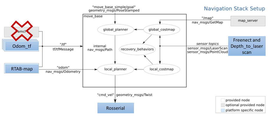
Figure 2 - How Packages works together.
All the implemented nodes in the Navigation Sack are in the mov_base package, but to make it work properly is necessary to configure some parameters, there is a bast list of them so in order to understand its role in the system you must know that to navigate the robot create three maps:
- Occupancy map, where all the static elements of the environment are represented.
- Global cost map, based on the first one, here an area around the objects are generated to "tell" to the global path planning to not make movements there, so the robot is safer from hitting anything.
- Local cost map, like the previous one, but in this case, the safe area are generated in "real-time" around a certain radius from the robot, its purpose is to avoid local dynamic objects, like a dog, or your grandmother moving around.
There are configurations that affect both maps, and those are:
- Obstacle_range: maximum rango to detect objects in meters.
- Raytrace_rangel: maximum range detection of free space around the robot.
- Footprint: coordinates in meters that contain the base's area of the robot.
- Footprint_inflation: Safe area around the robot.
- Inflation_radius: maximum distance of an obstacle to generating a safety area.
- Max_obstavle_heigh.
- Min_obstacle_heigh.
- Observation_sources: these are the list of sensors and their characteristics used to generate the maps.
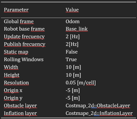
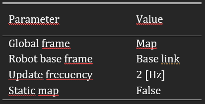
The parameters that affect the global cost map are:
- Global_frame: it defines the vectorial space (coordinate system) that is used for the maps.
- Robot_base_frame: reference frame for the maps that specify the pose of the robot's base.
- Update_frecuency: map's update frecuency in hertz.
- static_map: it tells if the cost maps must be loaded or not based on the previous ones (if there are any).
The parameters that affect the local cost map are:
- Rolling_window: indicate if the local map keeps its relative position in the center of the robot or not.
- Width: width of the map in meters.
- Height: height of the map in meters.
- Resolution: meters per grid.
- Origen_x: map's origin coordinate x.
- Origen_y: map's origin coordinate y.
- Obstacke_layer: the layer of the map with the obstacles.
- Inflation_layer: the layer of the map with the safety areas.
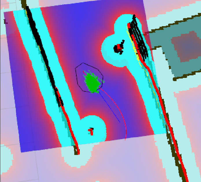
In Figure 3 you can appreciate the global cost map in light blue, the local cost map in the purple area, and the occupancy map as all the ground in grey, and all the objects in black.
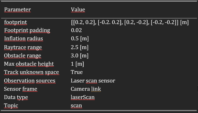
The values that I used are:
Hardware
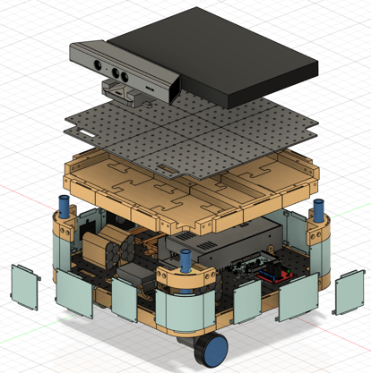
Here three topics are presented, the CAD model, the 3D print parts, and the electronics, for the first one I must say that all the modeling was made with Fusion360 (student license, although there is a free license with like one year of use).
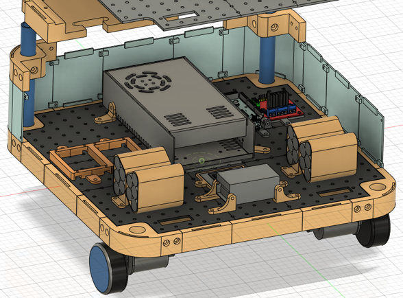
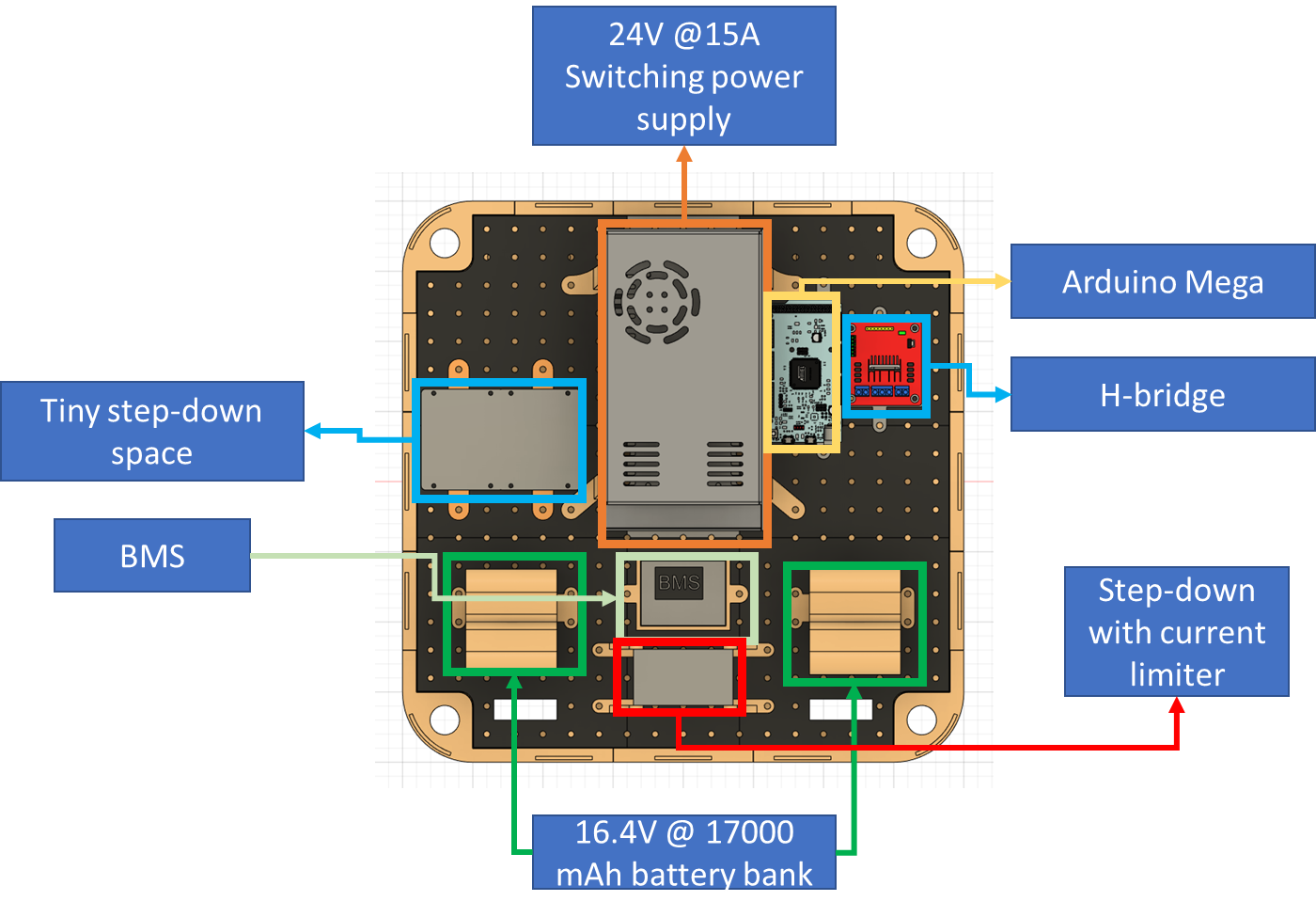
I want it to be easy to modify for others, that's why I designed the base with various interchangeable parts, so if you want to add some feature that needs to put something in the case, the process shouldn't be a headache, similarly, all the electronics are attached in platform with a pattern of holes for the same reasons, in the Figures 4, 5, 6 and 7 you can see the 3D model representing all of this.
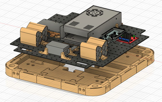
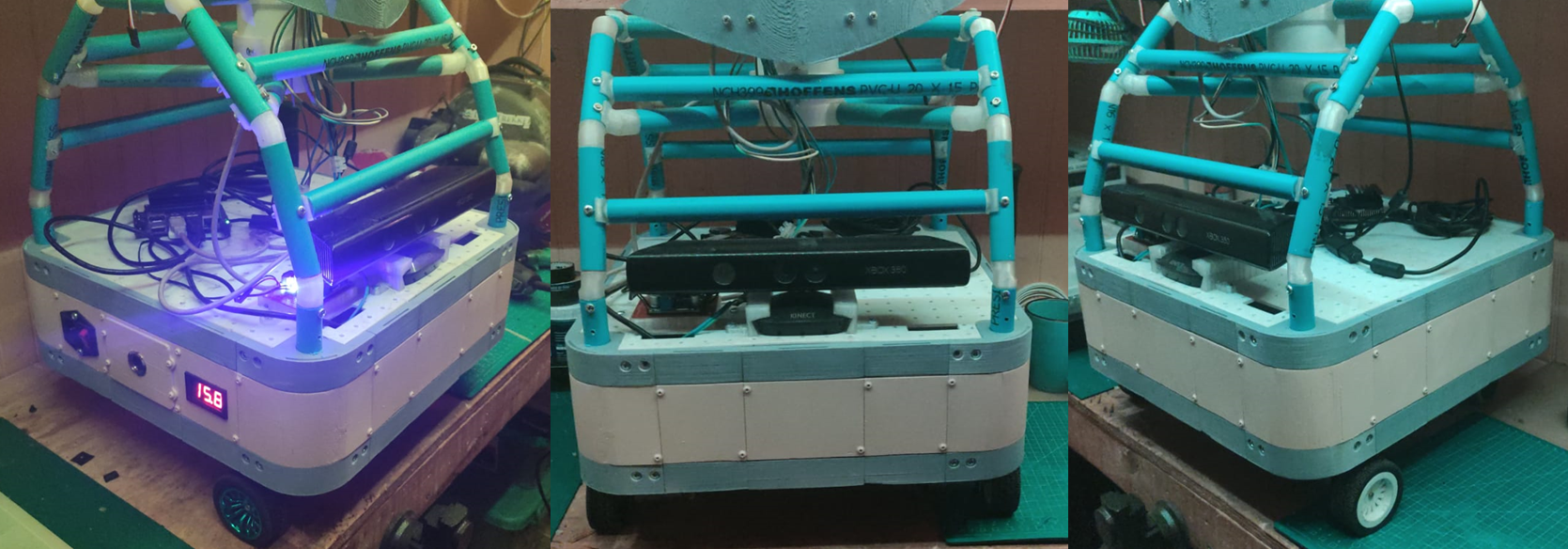
In Figure 8 you can see how it looks in real life.
As regards electronics there are several considerations to take, in the mobile base are all the main components for energy regulation and distribution to all the components in the rest of the robot, to accomplish this task a battery bank with 16.4V @17000 mAh is made from 20 NCR18650 wichs allows approximately one and a half-hour of autonomy, these batteries has a recharge cycle and the manufacturer [8] recommends a current of the 0.5 times the capacity of the battery, if you observed the Figure 6 there are two components to accomplish that, the BMS regulate the charge of a set of 4 NCR18650 per stage by voltage levels and the step-down based in the XL4016 [9] limits the current along the way with the voltage to the maximum allowed for the BMS, which is 16.8V [10].
A lot of elements need different levels of voltage to work, for example, one sensor works with 3V3 meanwhile the other needs 5V, one type of regulation that can be useful can be based on the LM78XX series [11] because it can have an output between 5V to 24V (depends on the model), and although they can keep a 4% of output tolerance and has overcharge protection they use is very limited to the 1A of supported current to the load, another good option can use Buck's modules based on the LM2596S [12] which is synchronous converter at 400 kHz with an output range of 1.2V to 34V (4% tolerance as well) with constant 3A, the power dissipation is internally regulated and generally is very efficient (even with the generated heat).
References
[1] http://wiki.ros.org/rosserial
[2] http://wiki.ros.org/freenect_launch
[3] http://wiki.ros.org/depthimage_to_laserscan
[5] http://wiki.ros.org/move_base
[6] http://wiki.ros.org/rtabmap_ros
[7] https://github.com/ros-visualization/rviz
[8] https://www.batteryspace.com/prod-specs/NCR18650B.pdf
[9] http://www.xlsemi.com/datasheet/XL4016%20datasheet.pdf
[10] https://www.mantech.co.za/datasheets/products/BMS-40A-4S_SGT.pdf
[11] https://www.mouser.com/datasheet/2/149/LM7812-461970.pdf
Discussions
Become a Hackaday.io Member
Create an account to leave a comment. Already have an account? Log In.