Close
0%
0%

OMNi

A modular, semi-autonomous, omnidirectional robot for telepresent applications

Similar projects worth following
OMNi is an open-source robotic platform that uses omni wheels to autonomously navigate tight and congested indoor environments. OMNi is being developed as a robot assistant to both the staff and visitors of museums. Our modular design allows for the rapid exchange of sensors and manipulators to suit any challenge: from running diagnostic tests and repairs on exhibits to offering tours and increasing accessibility to all individuals through telepresent interactions

We are however cognizant of our niche use case and realize the potential for this robot beyond museum applications. For this reason, we've specifically designed the robot to be modular and reconfigurable. Using the underlying autonomous navigation architecture this robot can be reconfigured as a health assistant in aged care facilities, an education platform for students, an information kiosk, or a waiter that autonomously delivers food at a restaurant while providing customers with a unique dining experience

October 2022 Update

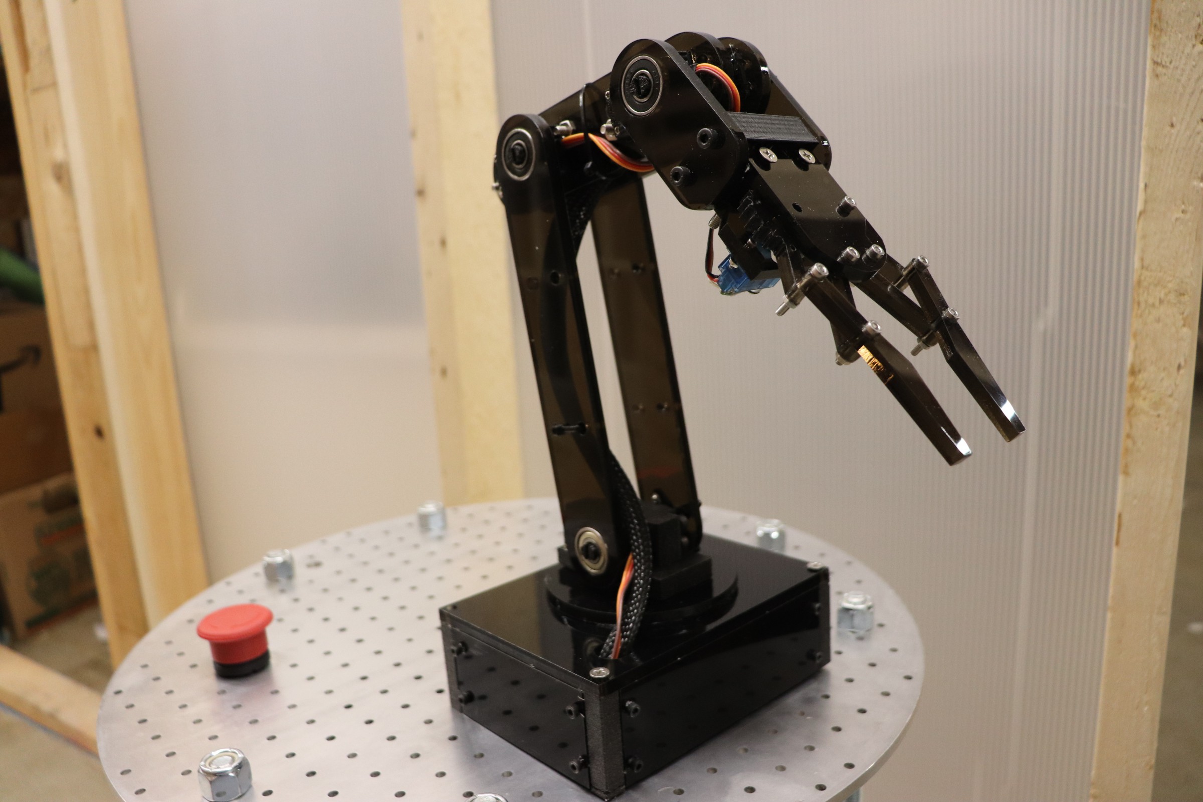
We're releasing the robot! Through the end of 2022 videos will be documenting the build process of OMNi and we are also going to be releasing the CAD, electronics, and software on GitHub. The first video is available below, providing a project overview and desired design improvements to OMNi. These improvements will be addressed over the following videos as OMNi is rebuilt from the ground up. Follow along for the journey!

If you want more details right now check out the past build logs covering the initial prototype development down below!
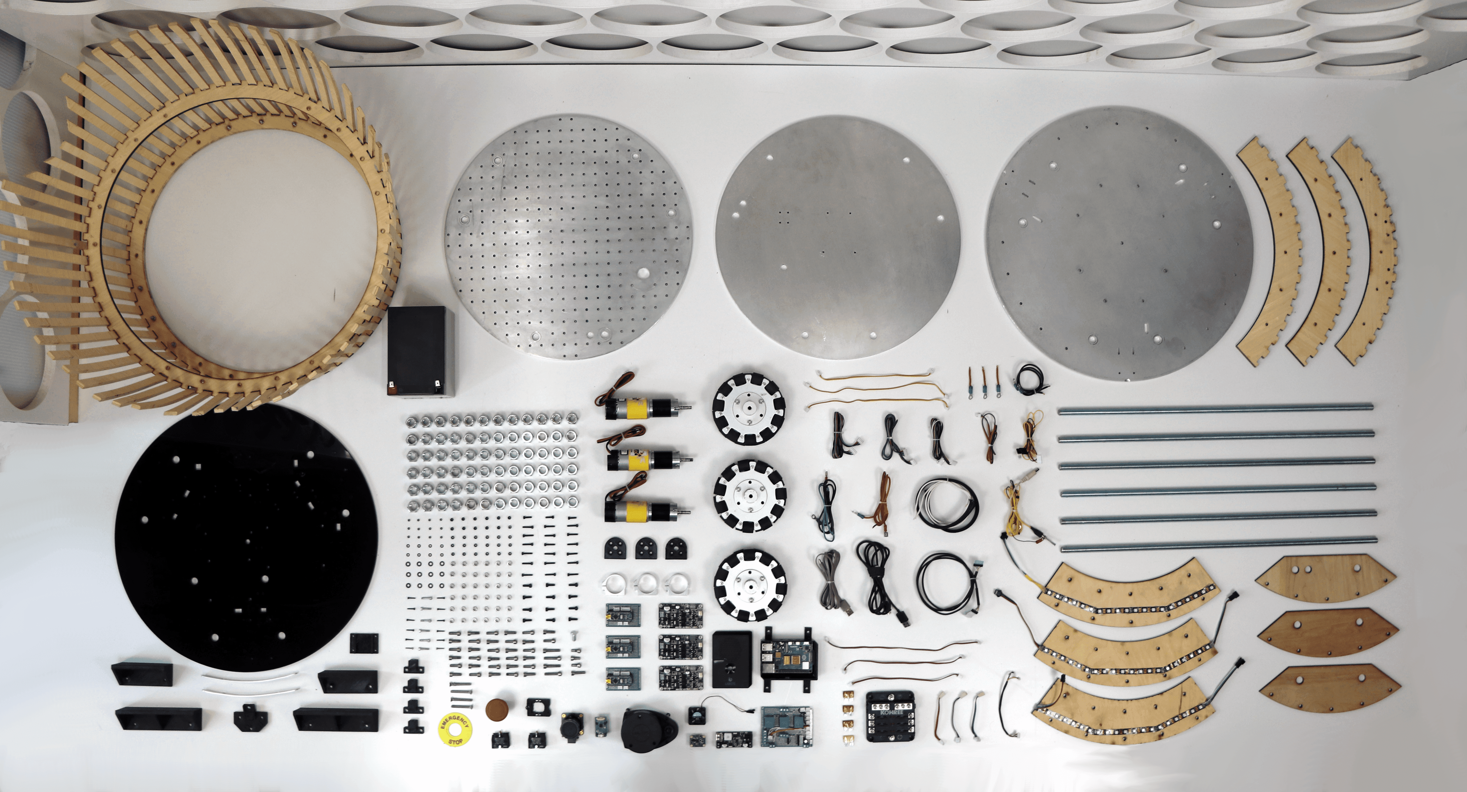
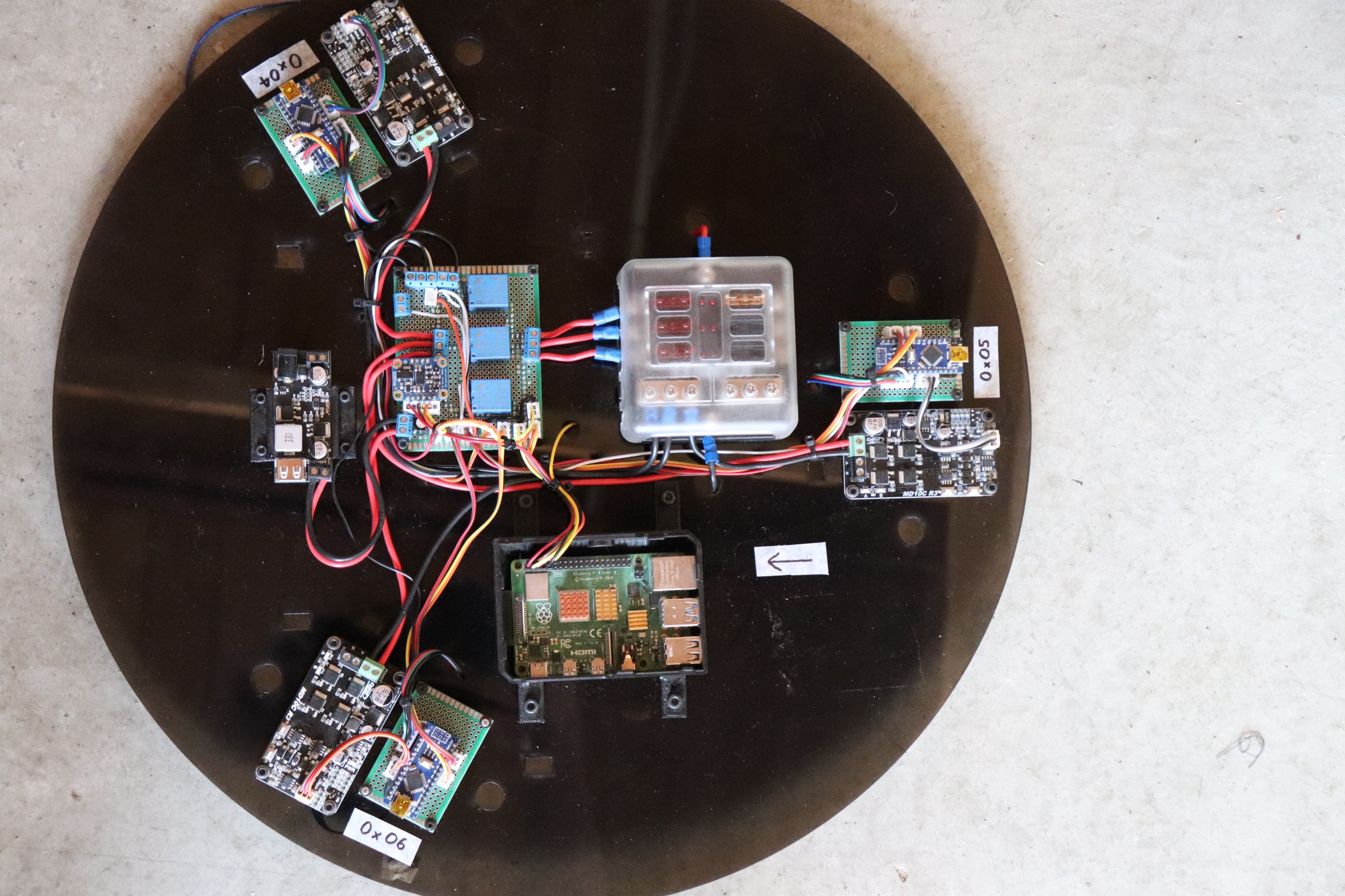
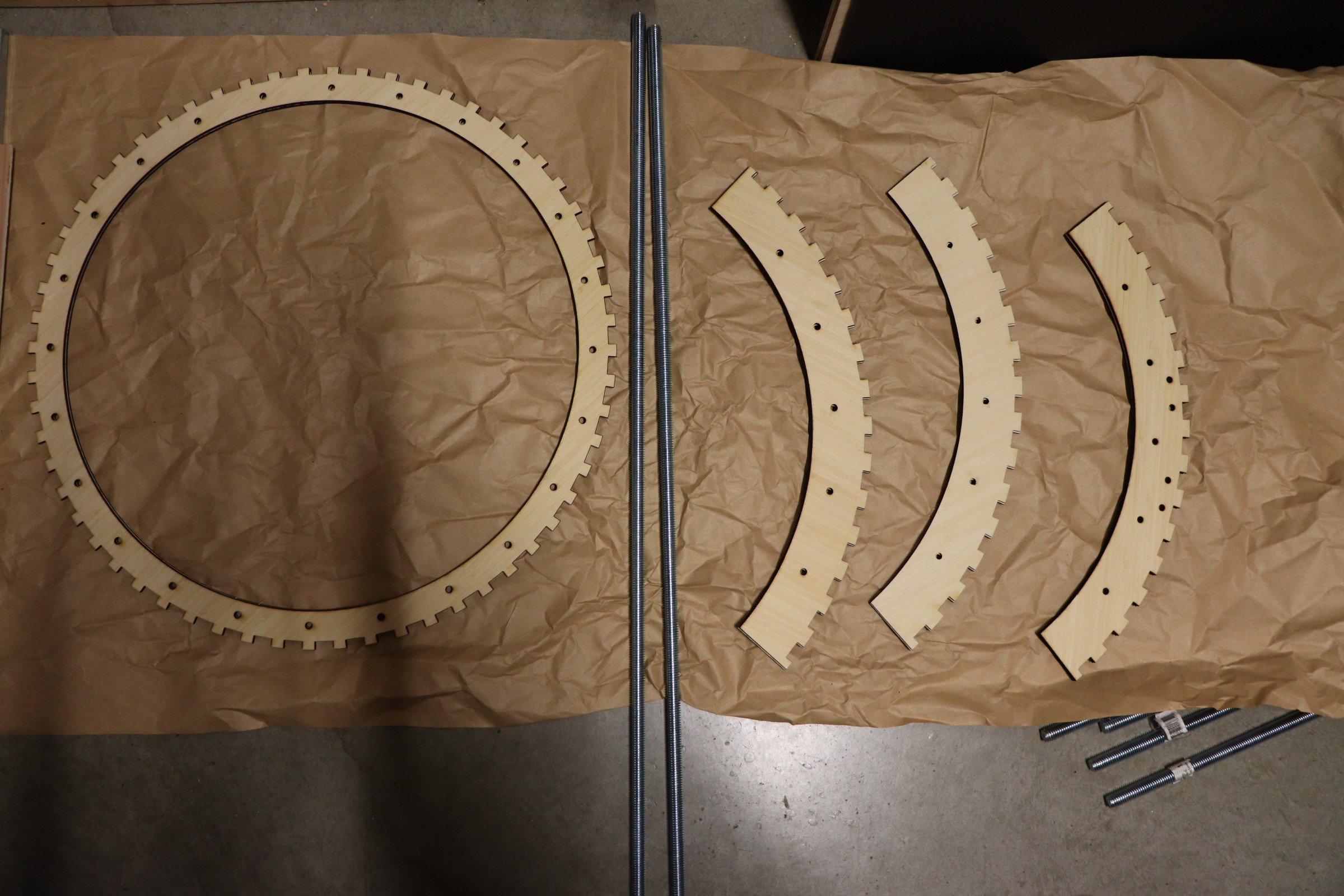
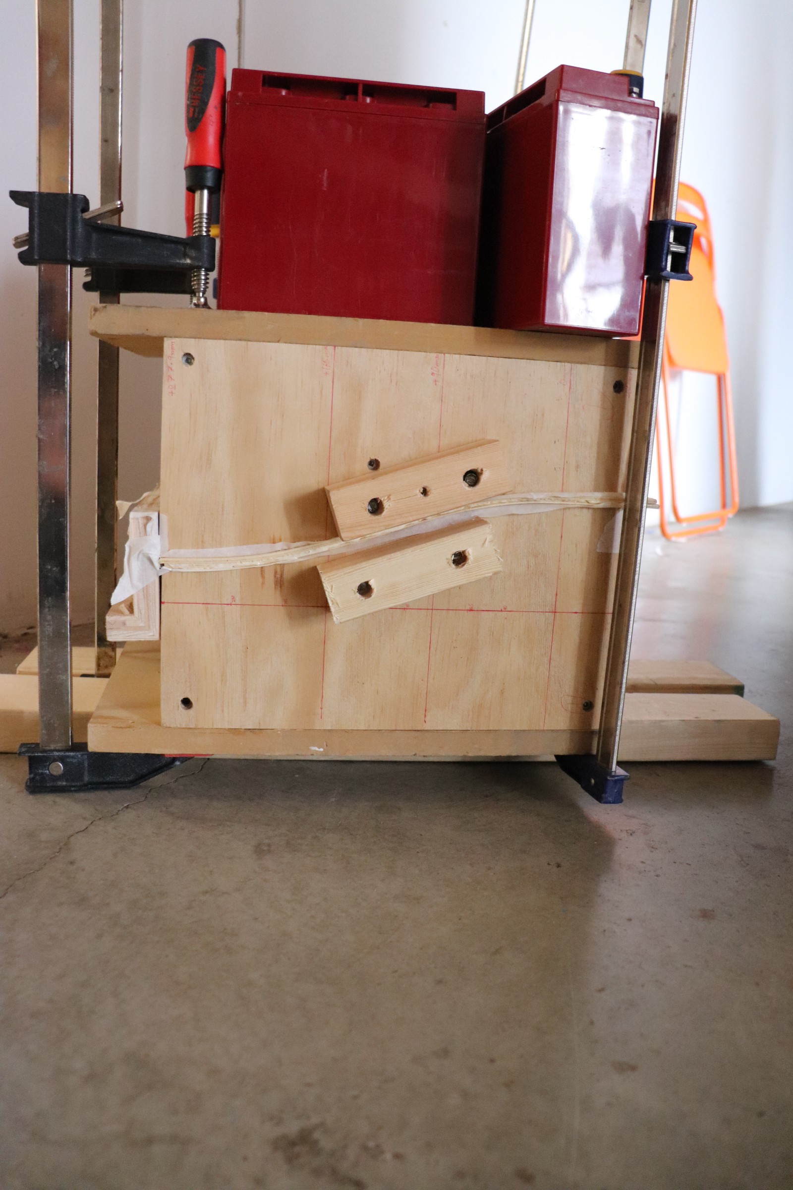
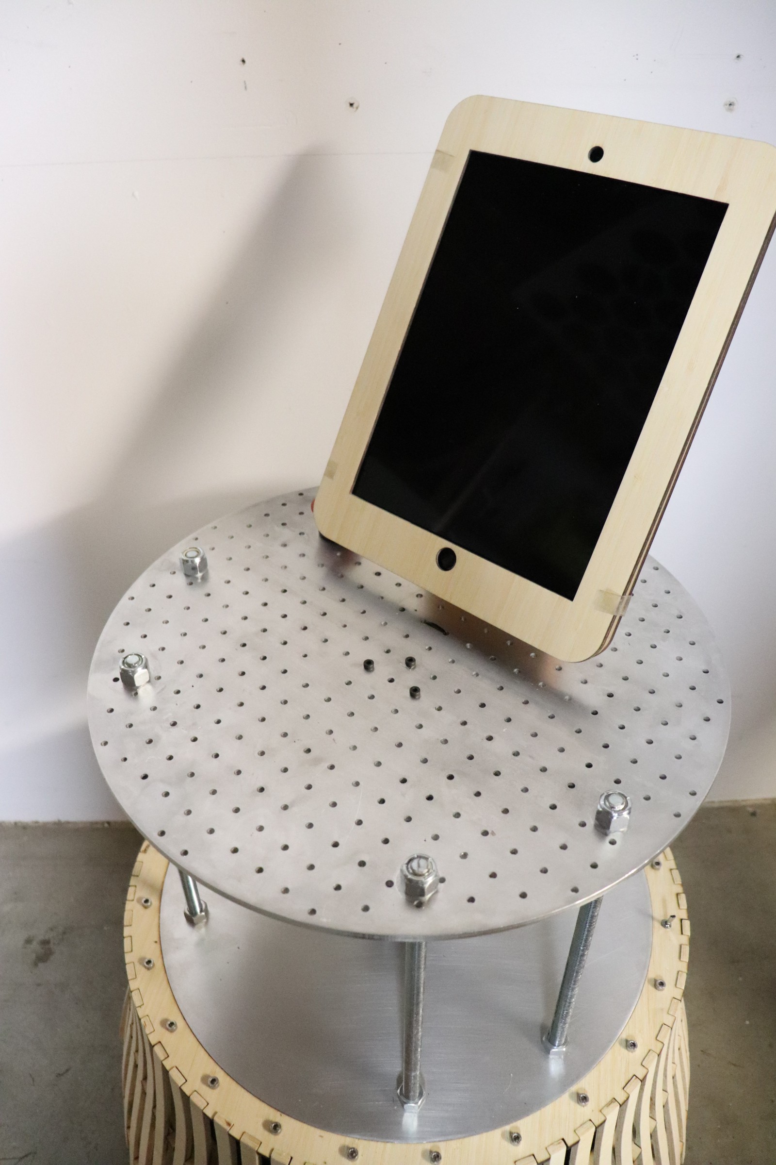
Always be knolling!

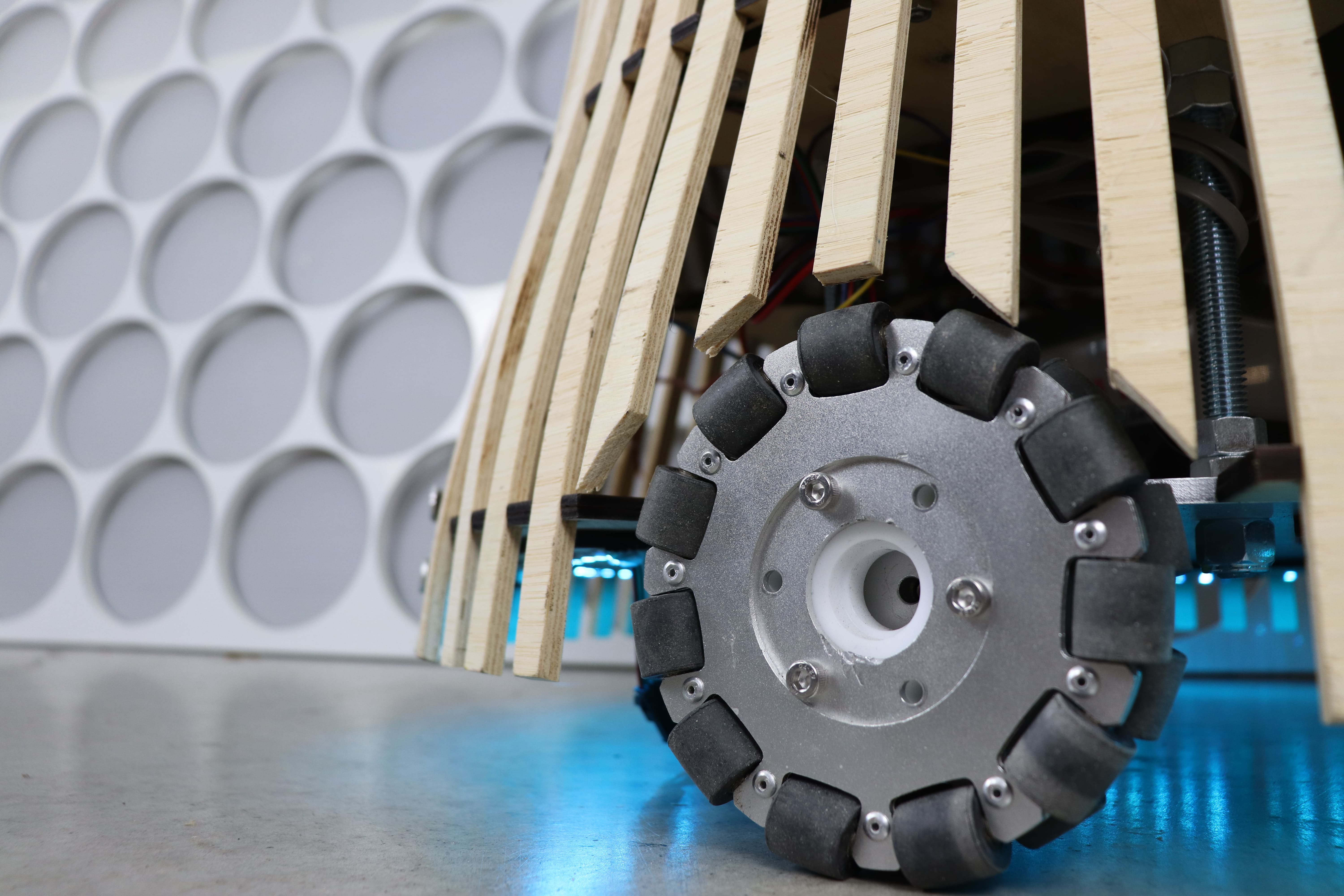
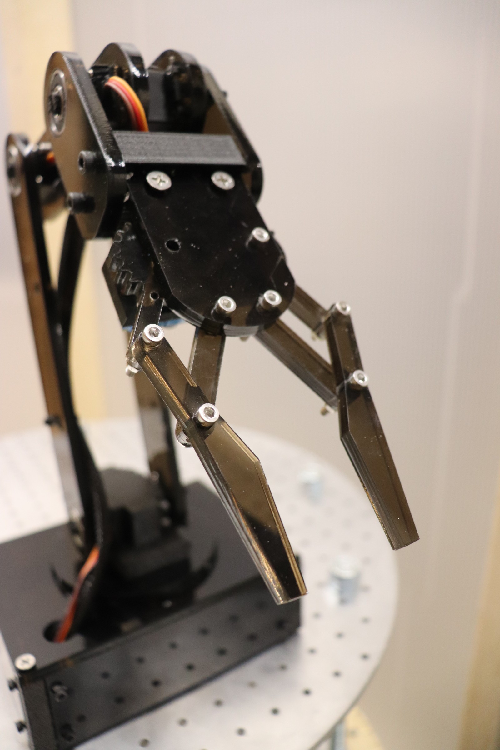
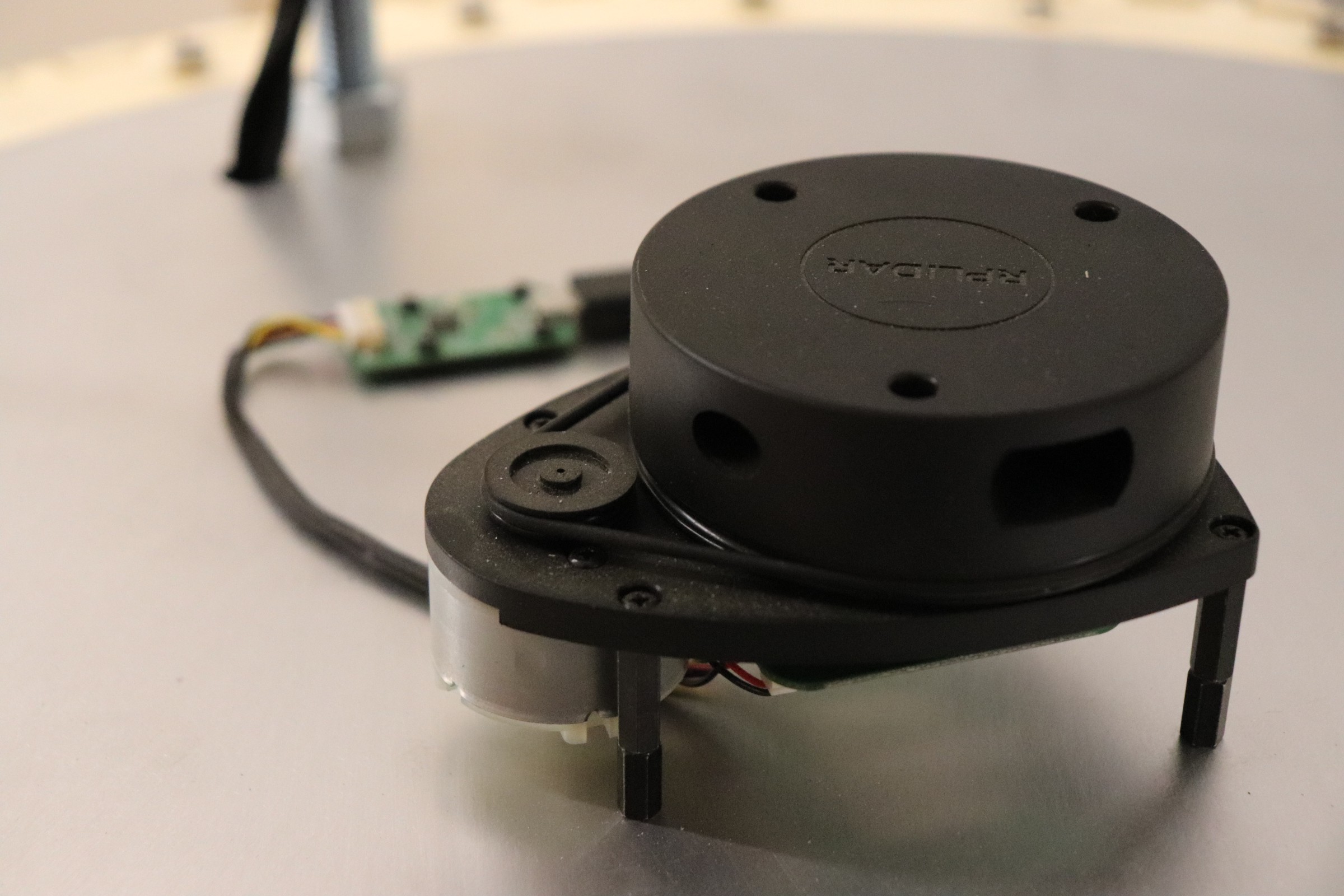
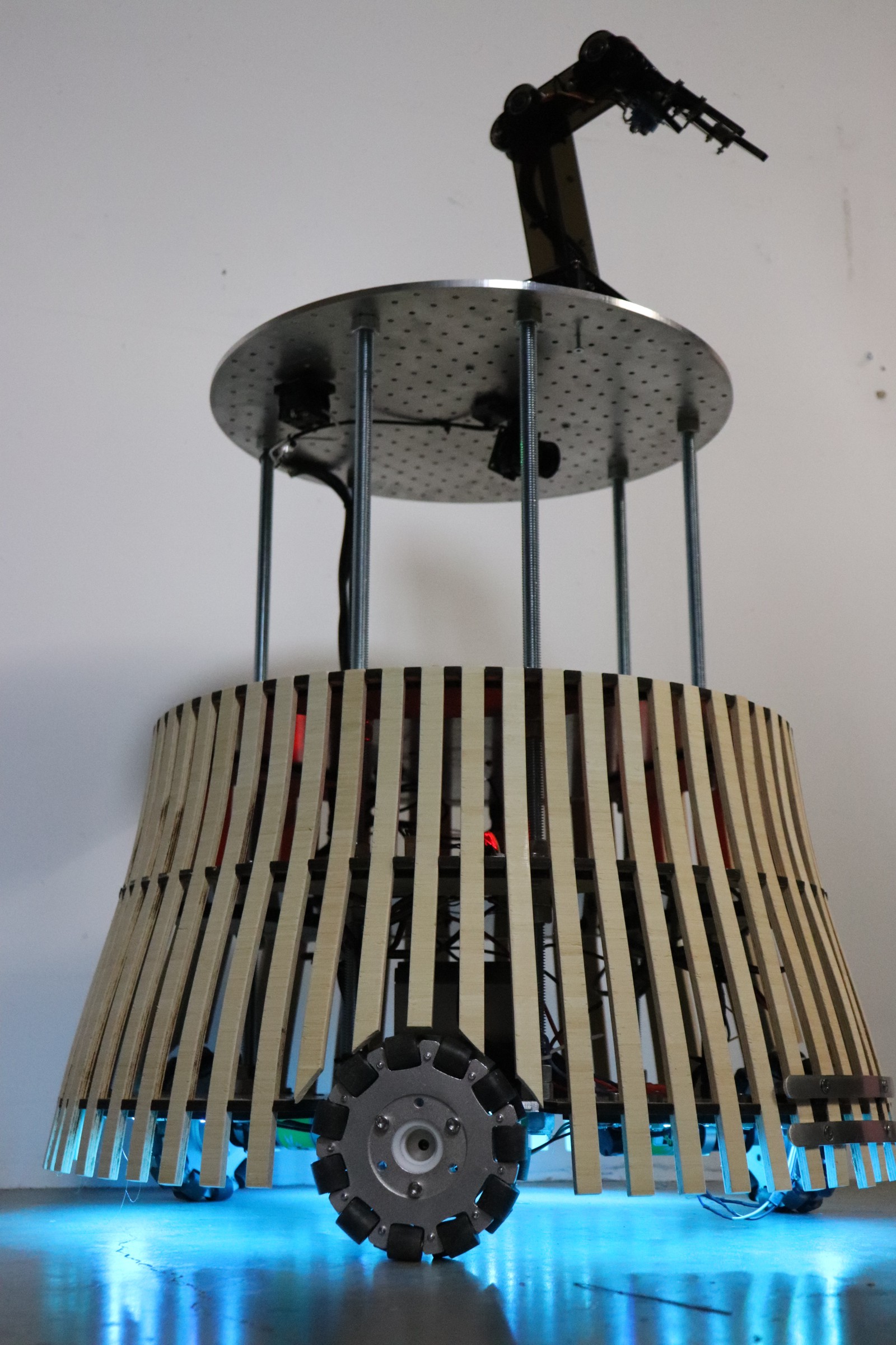
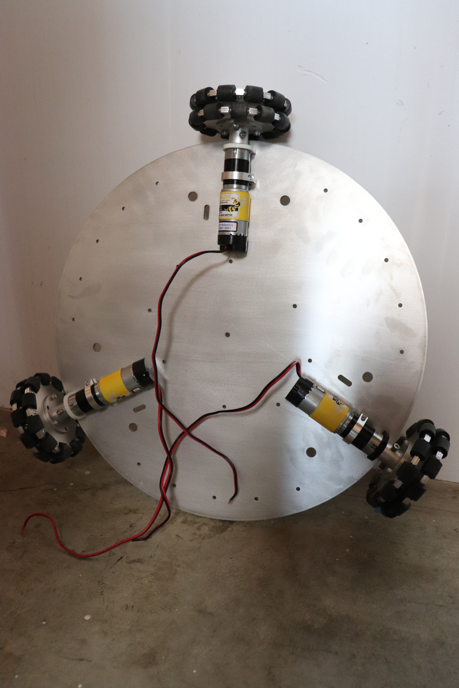
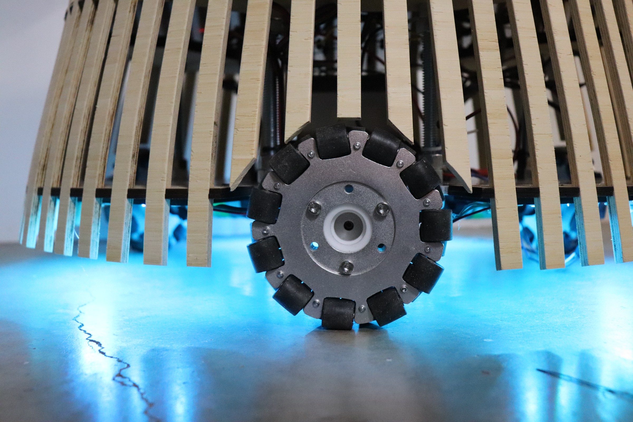
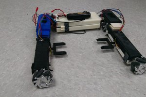
Close up of omni wheel drive


The Case for a Museum AV Support Robot

EDM Studio is a Vancouver-based studio that focuses exclusively on the design, development, and support of interactive digital media for cultural museums and science centers. Over the last 15 years, we have worked on all kinds of exhibit projects, from single kiosks in small regional museums to large redevelopments like Calgary’s Telus Spark, the Museum of Australian Democracy in Canberra, and the Canada Science and Technology Museum in Ottawa. 

The visitor experiences we’ve worked on are as varied as the locales. We’ve created an immersive mineshaft exploration, a broadcaster exhibit where visitors record color commentary for Olympic events, a touchscreen kiosk exploring the local implications of sea-level rise, an energy conservation interactive that introduces the concept of “vampire current”, an RFID-mediated experience that allows teams of students to follow a self-directed learning trail, etc.

These experiences leverage technology – computers, touchscreens, projectors, audio, associated physical interfaces – with the goal of providing an intuitive, enjoyable experience for the visitor. Which is all very fine … until something goes wrong. Over the last few years, we have slowly built up a wishlist for an audio-visual support robot. Here are a few use cases:

  • Rather than relying on a museum staff member doing “morning rounds’ to check all equipment, have a robot visit each screen in turn, confirm it is on, and displaying the expected content. For bonus points, physically tap the screen with a stylus and confirm it responds to touch. 
  • Staff reports an issue with a specific exhibit. All seems to be working when viewed through Remote Desktop. We need a remote set of eyes and hands … so we navigate the robot out to the exhibit, troubleshoot the problem, and report back. For bonus points, we instruct the robot to autonomously go to the exhibit and let us know when it is ready.
  • We recently deployed an exhibit that uses a retroreflective ball on a wand as a means of interacting with a virtual wildlife scene. Recalibrating the scene requires someone to physically wave the wand around the space. This is a job for a robot.

While these are (actual) audio visual-specific use cases, other visitor-centric uses are easy to imagine:

  • Telepresence, for example, a remote visitor is able to explore the museum from afar. 
  • Wayfinding robot able to guide people to specific exhibits.

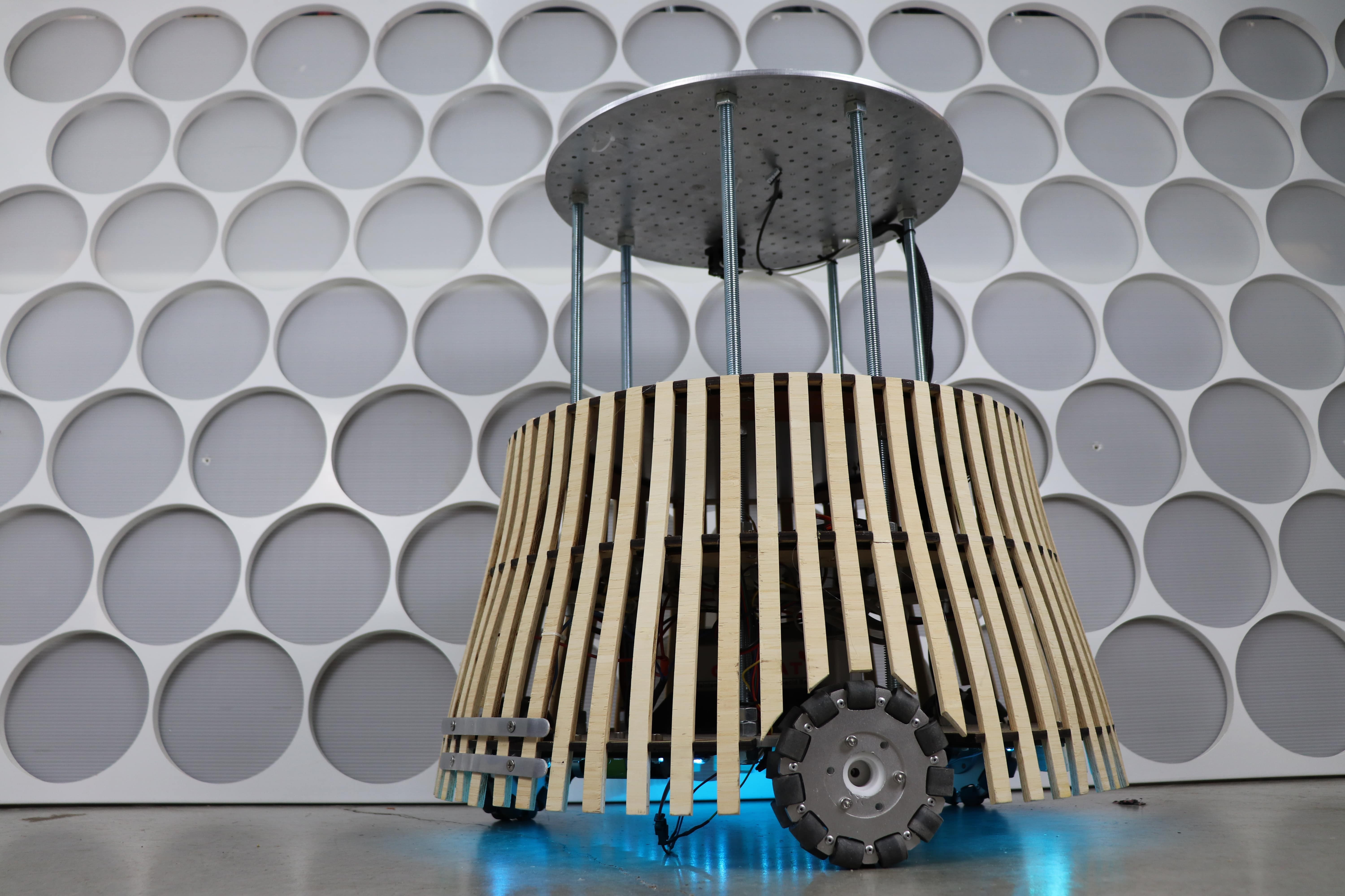
Museums offer a wonderful environment for the development of assistive robots. OMNi is our team’s attempt to realize this goal. Over the next couple of months, we will be taking our development platform into an actual museum for testing and feedback.

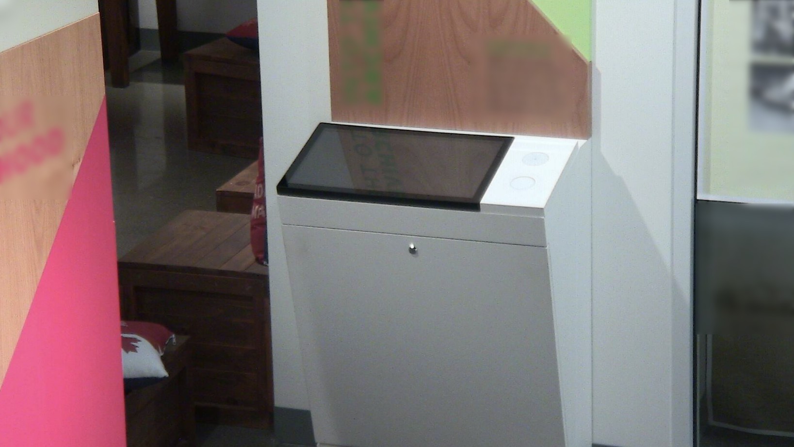
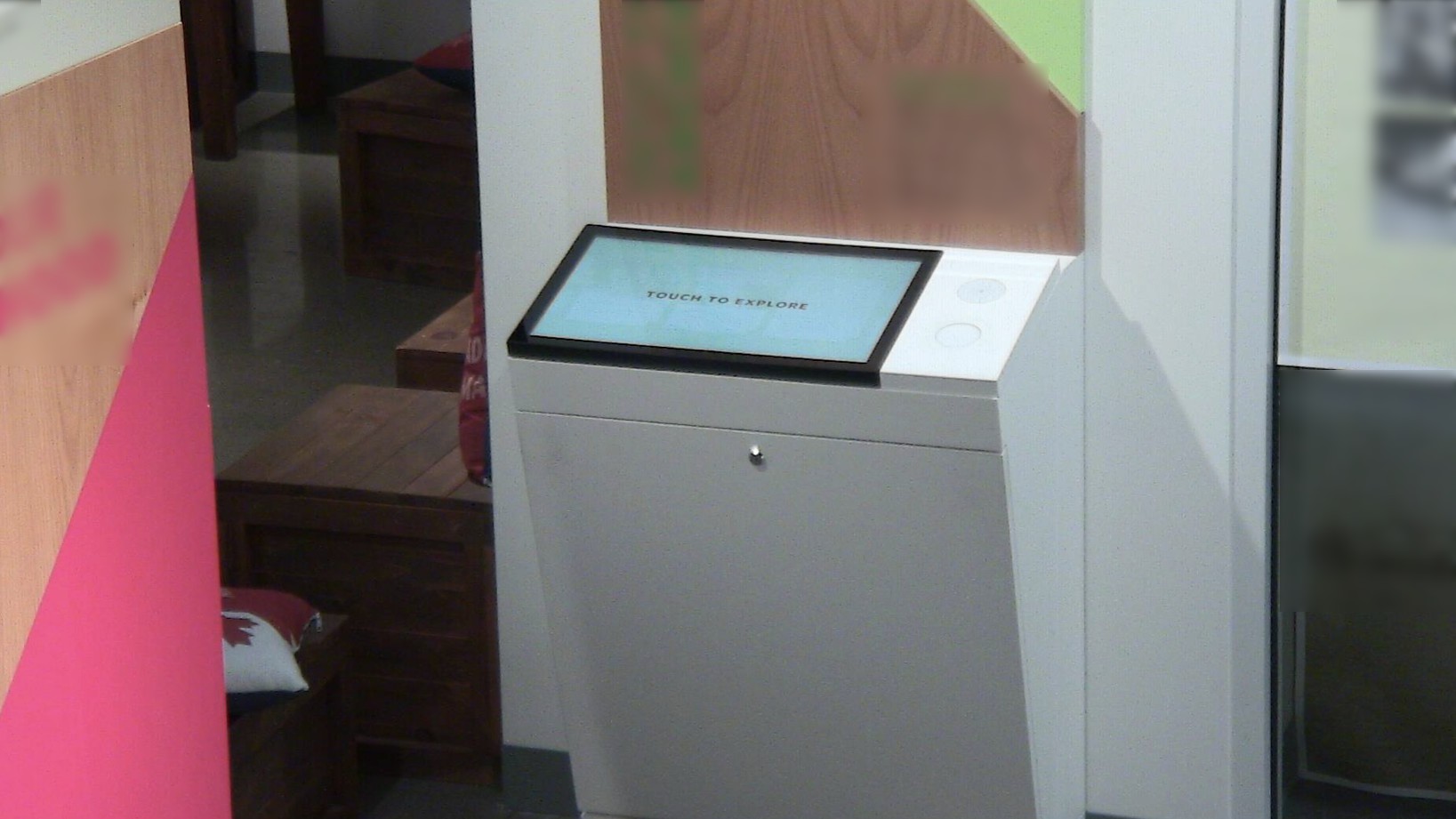
Mockup of OMNi interacting with a touchscreen kiosk at JUMP, Boise.

  • Museum Use Case: Concrete Example

    Darran Edmundson09/29/2021 at 06:59 0 comments

    We received an issue report yesterday from one of our museum clients saying that a touchscreen kiosk was out of service. In this particular museum, we have have PTZ cameras that allow us to remotely put eyes on the various exhibits. Here's what we saw (note, I've purposefully blurred the graphic panels and screen text in these shots) ...

    Indeed the screen is dark.  However, viewing that computer through Remote Desktop, the interactive application is running.

    In fact, from the computer's perspective, the touchscreen is detected and the above "Touch to Explore" screen is being sent via the graphics output . And the screen responds to status requests saying that it is on. Everything seems to be working fine ... except it obviously isn't.

    I won't go into the gory details but there is a strange interaction here between the computer's operating system and the touchscreen's firmware. Power cycling the computer resolves the issue (see below).

    The only way to detect this problem is to set eyes on the computer. Now in this case we have PTZ cameras in place and could implement a scheduled camera capture and a heuristic check to confirm the screen is on. ... but this isn't the norm.

    Having our OMNi robot do rounds is a very real need that can help detect exhibit issues before they impact the visitor experience.

  • Licenses and permissions

    Will Donaldson09/26/2021 at 21:49 0 comments

    We intend to release the entirety of this project as open-source, however, we are still working on polishing the code and touching up the CAD models before sending it off into the wild. In the coming weeks as this data is released we will be publishing under a Creative Commons - Attribution - ShareAlike 3.0 license.


    Below are a list of dependencies this project is built on and their associated licenses:

    ROS2 packages:

  • Charging Station

    Will Donaldson09/26/2021 at 21:35 0 comments

    Any truly autonomous vehicle should have the ability to self-charge, we are currently in the process of developing a magnetic docking station.

    The render below shows the two charging plates that protrude beyond the frame of the robot. We have machined these plates out of aluminum with countersunk bolts that crimp ring connectors can be attached to with wires that lead to the battery via a short circuit protection circuit. There will also be 3 small neodymium magnets per charging plate to ensure a reliable contact, however, experiments will need to be conducted to identify the appropriate magnet that is not so strong that it drags the charging station away with it. 

    Below is a render of the charging station. The curve has a radius slightly larger than that of the robot to ensure that if the robot comes in slightly misaligned it can push itself into the center of the curve. The backside of the charging station is at 90 degrees and is intended to be placed in the corner of a room. This serves two purposes, firstly, charging the robot in the corner of a room keeps it out of the way when not in use. Secondly, it ensures the robot cannot accidentally push the charging station away since it is firmly wedged in a corner.

  • Robotic Arm

    Will Donaldson09/26/2021 at 21:34 0 comments

    For our specific application, a robot for interacting with physical displays in a museum, a robotic arm is crucial. But beyond our niche application, having a modular robotic arm enables numerous possibilities for OMNi as an open-source platform. For example, a robot with an arm could act as a companion and caregiver in aged care facilities, automate mundane tasks in industry, and even act as a robotic waiter in specialized restaurants.

    Robotic arm

    The current robotic arm uses four MG996R servos for the arm and one SG90 servo for the end effector. Long term we plan to either develop a new, more robust, and capable arm with force sensors to provide haptic feedback to operators or look at implementing a compatible open-source arm that already exists. Modularity is very important to our design and we want OMNi to work with other open-source projects, actuators, and sensors. 

    Below are several pictures of the current arm. It is fabricated from laser-cut acrylic and 3D-printed brackets. One novel feature of the design is a custom printed frame for the servo that allows a bearing to be connected providing support on the opposite side of the servo to the output shaft. This design was adopted from a previous robotic snake project.

    While the arm is a good proof of concept prototype, there are several constraints that prevent it from being a useful tool including, a low load capacity, no feedback sensors, and low positional repeatability. Furthermore, we would like to develop an arm with interchangeable end effectors such as a gripper, stylus, and RFID tag.

    3D printed modified MG996 Servo case to fit a standard 608 bearing
    Servo with 608 bearing attached
    Servo with bearing in situ

    While the arm is a good proof of concept prototype, there are several constraints that prevent it from being a useful tool including, a low load capacity, no feedback sensors, and low positional repeatability. Furthermore, we would like to develop an arm with interchangeable end effectors such as a gripper, stylus, and RFID tag.

    The gripper is a linkage system driven by a single actuator

  • Telepresent Operation

    Will Donaldson09/26/2021 at 21:34 0 comments

    As powerful as autonomous SLAM navigation algorithms are, sometimes having human operators is required. An example may be for visitors to museums, or other events, that wish to self-guide their own tour while also interacting with the exhibits, however, are unable to visit themselves due to age, sickness, or other accessibility constraints.


    OMNi offers two methods of user control: handheld controller or keyboard. We currently use a Xbox One controller that connects to the robot via Bluetooth for operating the robot when within about 10 meters.

    XBox One controller

    Alternatively, by using a ZeroTier SSH connection between the robot and a remote computer. The advantage of using ZeroTier software is that it offers a secure connection that can be connected to any internet network globally. The one caveat is that, currently, the remote machine must be configured to run ROS2 and have the OMNi workspace installed and configured. As this project continues to develop we will publish detailed instructions on how to achieve all this.

    Once connected to the robot on a remote computer, we use the ROS2 package teleop_twist_keyboard (BSD License 2.0). As shown in the README file of the previous link the robot can be controlled using nine keys (uiojklm,.) in either holonomic (omnidirectional drive) or non-holonomic (traditional drive, like a car).


    However, driving the robot from a remote location means that you cannot see the robot nor the environment. As such, we installed a Raspberry Pi High Quality Camera on the top platform so that the operator can have a first-person view of the robot. Raspberry Pi High Quality Camera

    Raspberry Pi High Quality Camera

    Below is a demonstration of what the first-person view looks like from a remote computer.

  • LiDAR, Mapping, and SLAM

    Will Donaldson09/26/2021 at 21:33 0 comments

    Future project logs and build instructions will go into greater detail as to how ROS2 based SLAM (simultaneous location and mapping) algorithms generate maps, but the fundamental principle is that by tracking the location of the robot using sensor fusion (as discussed in the last project log) subsequent LiDAR scans can be overlayed one on top of the other matching together similar features: the corner of the room, or a doorway in the wall. Overlaying subsequent laser scans is analogous to building a jigsaw puzzle.

    The picture below shows the robot traveling towards the left, behind it on the right shows a solid map based on previous LiDAR scans while further down the hallway to the left there has been no map created (yet) since the LiDAR sensor has not scanned this region.

    Scanning the hallways of the building that OMNi is being developed in

    Below is a video demonstrating the mapping process. The robot is being manually driven around the environment using a Bluetooth Xbox One controller.

    Alternatively, instead of manually driving the robot around we can use the ROS2 navigation package to autonomously drive to different waypoints while avoiding obstacles.


    It is worth noting that these videos were recorded on the first version of the robot. Now that the second version of the robot has a platform above the LiDAR platform there are six poles that partially obstruct the LiDAR scan. This problem can clearly be seen in the picture below. The red dots represent the current LIDAR scan, several of which are located at the thin, vertical, yellow poles. In its current configuration, this would cause erroneous behavior as the SLAM algorithm would interpret that the robot has somehow passed through an obstacle. To mitigate this problem we are using the laser_filters package to remove data points closer that a certain range.

  • Sensor Fusion

    Will Donaldson09/26/2021 at 21:33 0 comments

    For a robot to successfully navigate through an environment it must know its position relative to both its environment and its previous state(s). Generally speaking, robots require multiple sensor inputs to locate themselves. LiDAR is a powerful technology for mapping the surrounding environment, however, a severe limitation is that the LiDAR scan is very slow, updating between 1 - 10 Hz. For a robot that is moving at a walking pace, this is not fast enough to precisely and accurately respond to a dynamic environment. For example, if the LiDAR scan is only updating once per second and the robot moves at a speed of 1m/s then a LiDAR scan could determine that the robot is 0.75m away from a wall and before the LiDAR scan updates the robot will have already collided with the wall, believing it is still 0.75m away from the wall based on the previous LiDAR scan.

    RPLidar A1 has a scan update frequency of 5.5-10Hz

    To overcome this limitation our robot needs to fuse together multiple readings from several different sensors to accurately predict its location at any time. To do this we have installed motor encoders to count the number of revolutions of the wheel, and thereby calculate the distance it has traveled, as well as an IMU (inertial measurement unit). Both these devices can be sampled on the order of 100Hz.

    By combining the high-frequency measurements of the encoders and IMU with the low-frequency LiDAR scans we can continuously generate an accurate location by interpolating the position of the robot between each subsequent LiDAR scan.

    The next blog post will discuss how we use the LiDAR sensor and build a map of the environment around the robot. The remaining of this blog post will focus on how we process the measurements from the encoders and IMU.

    While the previous paragraphs glorify the strengths of encoders and IMUs, we omitted their significant flaws. In order for a motor encoder to calculate an accurate location, we must assume a no-slip condition. That is to say that the wheel never slips on the floor; if the wheel were to slip then we get an inaccurate location measurement since the encoder believes the robot drove forward despite the wheel slipping and spinning on the spot. For most vehicles; cars, skateboards, and the Curiosity Mars rover, the no-slip condition is a fairly accurate assumption, however, given that we are using 3 omnidirectional wheels this is a little more nuanced. The entire premise of an omni wheel is that it works by spinning freely on the axis perpendicular to its rotation. Nonetheless, on a surface with a high enough coefficient of friction, we can use the equations of motion (below) to calculate the location of the robot based on the RPM (revolutions per minute) of the wheels.

    Equation of motion for a three omni wheel robot. Where r is the wheel radius and R is the wheelbase radius

    Our robot initially only relied on the motor encoders however when it came to navigating accurately we begun to notice erroneous behavior. Upon closer inspection, we noticed the wheels would slip on the polished concrete floor.

    <insert video of wheels slipping>

    To mitigate this we first created acceleration profiles, limiting the speed at which the motors could accelerate, thereby significantly reducing the wheel slip.

    To improve the results further we added the BNO055 IMU so we could combine the readings into a single odometry value using an EFK (extended Kalman filter).

    <TO DO: outline how the EFK works and associated matrices, discuss covariances>

  • Software Overview

    Will Donaldson09/26/2021 at 21:32 0 comments

    OMNi runs Ubuntu 20.04 with ROS2 Foxy Fitzroy. ROS2 is the second version of the Robotic Operating System, a benchmark platform for robotics in both academia and industry. The ROS2 architecture is to create a network of nodes with publisher/subscriber connections between the nodes.

    There is a significant amount of information regarding ROS2 and this post cannot contain but a sliver, we will highlight some different features but for more information, we advise consulting the documentation.

    A useful tool while developing this project has been to use rviz2 (a visualization tool for ROS2). Below is a screenshot of rviz showing a low poly model of the robot along with the transformation tree between the different frames. The below picture shows the /robot_description and /tf topics that are responsible for the graphical display of the robot and coordinate transformations, respectively.


    To demonstrate the powerful node structure we can add in a new topic, /scan, which displays a live view of the LiDAR scan. Every red dot in the picture below is a place that the laser has hit an object (such as a wall) and reflected back to the sensor. You can also see the map and odom transformations to the left of the robot, representing the map origin and the robot's initial location, respectively (assuming perfect tracking these two transformations would be in the exact same location).

  • Electrical Subsystem

    Will Donaldson09/26/2021 at 21:32 0 comments

    OMNi’s power comes from a CBL14-12 battery (12V 14Ah) with all components protected by a fuse block. The second platform of OMNi houses the electrical subsystem and unlike the other platforms is laser cut from black acrylic to avoid short circuits when mounting electrical components directly to the surface.

    Electrical subsystem mounting on acrylic platform

    The picture above shows the electrical layout with a 12V to 5V black voltage regulator in the center-left. Next to it is a circuit assembly that houses a BNO055 inertial measurement unit and 3 relays that carry power to each of the 3 motors via 3 separate MD10C motor drivers. Also in the center of the black acrylic platform is a 6-blade fuse box and the computer, a Raspberry Pi 4. Finally, there are 3 Arduino Nano boards around the circumference of the electrical platform.

    Using a 3.3-volt I2C bus (Inter-Integrated Circuit) the Raspberry Pi 4 communicates with the Arduino Nano boards, each with its own unique address (the Arduino in the picture below has an address of 0x06). Each Arduino Nano uses an interrupt service routine to measure the RPM of its respective motor and controls the speed using a closed-loop PID controller (proportional integral derivative).

    MD10C motor driver and Arduino Nano

    In the event, the robot needs to be stopped immediately there is an emergency stop button (normally closed) that when pressed cuts power to a set of relays (shown below), and thereby cuts power to the motors. This setup ensures the motors can be stopped immediately but it does not cut power to the Raspberry Pi, this is a useful design feature both while developing the robot as well as when it is deployed as it allows continued data logging of the event for later analysis if required.

    Voltage regulator (left) and protoboard with BNO055 IMU and motor relays

    Also in the picture above is a BNO055 IMU (inertial measurement unit). While more expensive than many other IMUs, the BNO055 was chosen as it calculates accurate orientation readings using sensor fusion algorithms on a high-speed ARM Cortex-M0 based processor. This small investment thereby significantly decreases the difficultly in programming and calibrating the robot as well as marginally reducing the computation load. 

    Underneath the robot, a ring of 60 RGB neopixels is attached, in addition to adding an aesthetic ambient light to the robot, these neopixels communicate information to people in the local vicinity. For example, in the future, the lights may gently pulsate while charging before turning a solid color when fully charged, alternatively the lights may turn red when the robot encounters an unexpected event or environment as a warning or error code.

    Neopixels installed under the frame
    Glowing neopixels

    Generally speaking, the sensor modules that can be attached to the robot (LiDAR, camera, robotic arm, tablet) and all self-contained subsystems and interface with the main electrical system via USB serial communication. 

  • Version 2 Hardware

    Will Donaldson09/26/2021 at 21:27 0 comments

    Version 2 of the robot has largely the same layout however we focused on creating an aesthetically pleasing robot shell that is friendly and inspires curiosity. The blog details the build procedure however it is a labor-intensive design, for this reason, we designed the mounting mechanism such that the wooden shell can be removed by unscrewing the bolts and replacing it with a different shell (i.e. a different, mass-produced shell).

    During our design process, we did create one design inspired by artist David C. Roy, however, due to the design complexity, we did not pursue it. Nonetheless, it is a design we would like to share in the video below. Unlike our static shell, this design would use an inner and outer shell spinning in opposite directions at a constant velocity creating an enchanting optical illusion.

    1/4" aluminium plate CNC fabricated
    Each piece is made of two laser cut 1/8" bamboo wood glued together
    Bottom platform
    Electrical platform
    Jig for curving two layers of 35x35cm 1/8" bamboo sheets
    Sheets of 35x35cm bamboo are bent and then cut down to 15mm strips
    Gluing bamboo strips to the laser cut bamboo rings (note that the bamboo rings lift up and over the robot allowing for access when servicing the robot)
    Hand cut strips to (approximately) match the curve of wheel

    CAM fabrication of top plate
    CAM fabrication of top plate
    Ipad bamboo frame

View all 11 project logs

Enjoy this project?

Share

Discussions

Similar Projects

Does this project spark your interest?

Become a member to follow this project and never miss any updates