 David Levi
To keep the MicroSynth simple and low profile, I experimented with using touch pads instead of mechanical switches. Other circuits can use capacitive sensors connected to microprocessors, but because this circuit is all analog and designed to be as simple as possible, I made a resistive, not capacitive, touch pad.
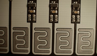
Here's what the first version of the touch pad looks like. Pressing a touch pad key with your fingertip allows a tiny amount of current to flow across the touch pad. This current is just enough to turn on a transistor. It's like a membrane button you'd see if you took apart a calculator, but your finger is the button pad. Where the black keys would be, you can see the individual transistors, with a capacitor and two resistors below.
Here is part of the schematic for the first version of the touch pad. When a NFET is turned on, it will connect the "Keyboard_Signal" net to ground with a certain amount of resistance. Q58 is a direct connection to ground, Q57 is 1K to ground, Q56 is 3K ohms to ground ect. Each 1K increment is equal to one musical semitone, but because I skip the black keys, it sometimes jumps by 2K instead of 1K ohms.
Now onto how these transistors actually turn on. The interlocking squiggle patterns A, B, C, represent the touch pads for keys A, B and C. When they are unpressed, they are just an open switch. But, when your finger presses onto them, it creates a resistance across two sides of the touch pad. Your finger turns the touchpad into a resistor of between maybe half a megaohm to a couple megaohm, depending on the person and how hard they press.
So, when the key is unpressed, it is pulled down by a large resistor (R74). When it is pressed, it is pulled up above the threshold voltage of the transistor, causing it to turn on and send a signal out to the "Keyboard_Signal" net.
But what's the purpose of the resistor and capacitor in front of the FET's gate? A FET transistor has very high impedance, and the signal will not be affected much by an extra 1M ohm. But what could effect the FET is electrostatic discharge.
The human body model of ESD models an ESD event as having 100pF of capacitance. The more capacitance, the more charge stored up. And capacitance is how much charge can be stored per volt (C=q/V). So, if we move 10 volts of charge from a 100pF capacitor to a 1000pF capacitor, the new larger capacitor will only have 1 volt charged up.
In the MicroSynth, I use a 4.7nF cap, a cap about 50 times larger than the human body model. So we'd expect a 8000 volt ESD zap to turn into 160V once it reaches the cap. The 1 M ohm resistor before the gate helps slow down the rate of charge and helps the ESD discharge through the pulldown resistor and the fingertip. Based on the simulations above, only 60V reaches the gate of the FET. This is still enough to cause harm, but luckily most discrete FETs have a built in ESD diode to protect against some amount of ESD. With all these parts in place, we don't have to worry about static electricity burning a hole in our transistor gate.
There's still things to improve with this circuit however. I apparently have relatively sweaty fingertips, so my resistance is lower on a touch pad. But my friends have drier hands, and need to press down harder to fully turn a key on. I'll be experimenting with different ways to increase the sensitivity of these keys. I can chose a power FET that has a lower turn on voltage, I could buffer the input with a BJT transistor to increase the overall gain, I could even pull the gate to just below its threshold level instead of all the way to ground.
But, this circuit definitely works. And it is so much cheaper and more fun than a regular old mechanical switch
Discussions
Become a Hackaday.io Member
Create an account to leave a comment. Already have an account? Log In.