 Usagi Electric (David)
This is an ongoing project that's definitely going to take a while!
Check out the build logs for all the proper info.
This is a 1-bit vacuum tube computer running at just +24V and -12V.
Already have an account? Log in.
To make the experience fit your profile, pick a username and tell us what interests you.
This is an ongoing project that's definitely going to take a while!
Check out the build logs for all the proper info.
|
octet-stream - 78.99 kB - 10/17/2021 at 16:16 |
|
We’ve got an architecture and we’ve got a basic low voltage tube inverter design, next we gotta figure how to take that inverter building block and transform it into our basic block diagram.
I love block diagrams, especially CPU architecture diagrams, but they’re not particularly helpful in telling you exactly how to build what you have to build. I know I need things like an ALU and a bunch of D Flip Flops, but how do I get there with just a single inverter? Well, an inverter is really just a simple logic gate. Whatever input is coming in, it inverts it to the opposite.
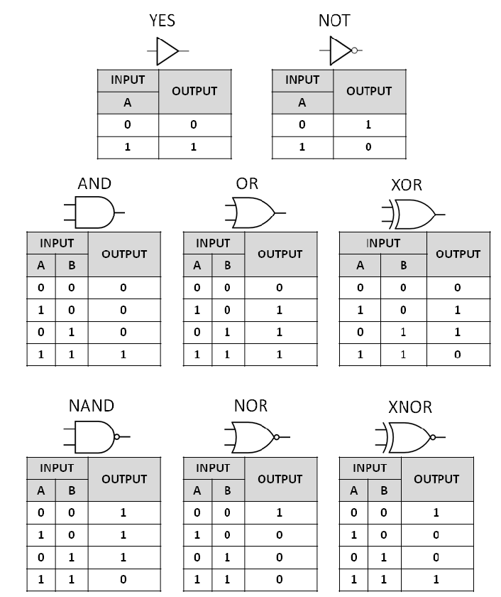
There are, in total, 8 logic gates we easily have at our disposal:
Inverter, Buffer, AND, NAND, OR, NOR, XOR, and XNOR
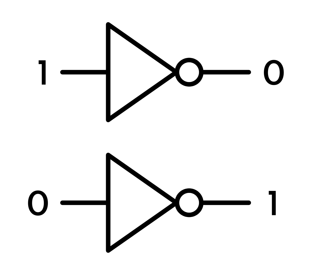
Inverter: If the input is low, the output is high, and vice versa
Buffer: Passes the input to the output, but makes it stronger
AND: If both inputs are high, the output is high, otherwise, the output is low
NAND: Same as an AND gate, except the output is inverted
OR: If either or both inputs are high, the output is high
NOR: Same as an OR gate, except the output is inverted
XOR: If both inputs are high or both inputs are low, the output is low
XNOR: Same as an XOR gate, except the output is inverted
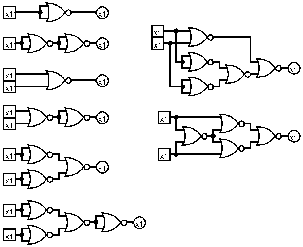
Out of all these gates though, the NAND and NOR gates are by far the most important, and that’s because they’re universal gates. That means that any other logic gate can be made from a combination of just NOR gates or just NAND gates! And famously, the Apollo Guidance Computer was built almost exclusively using dual 3-input NOR gate ICs.
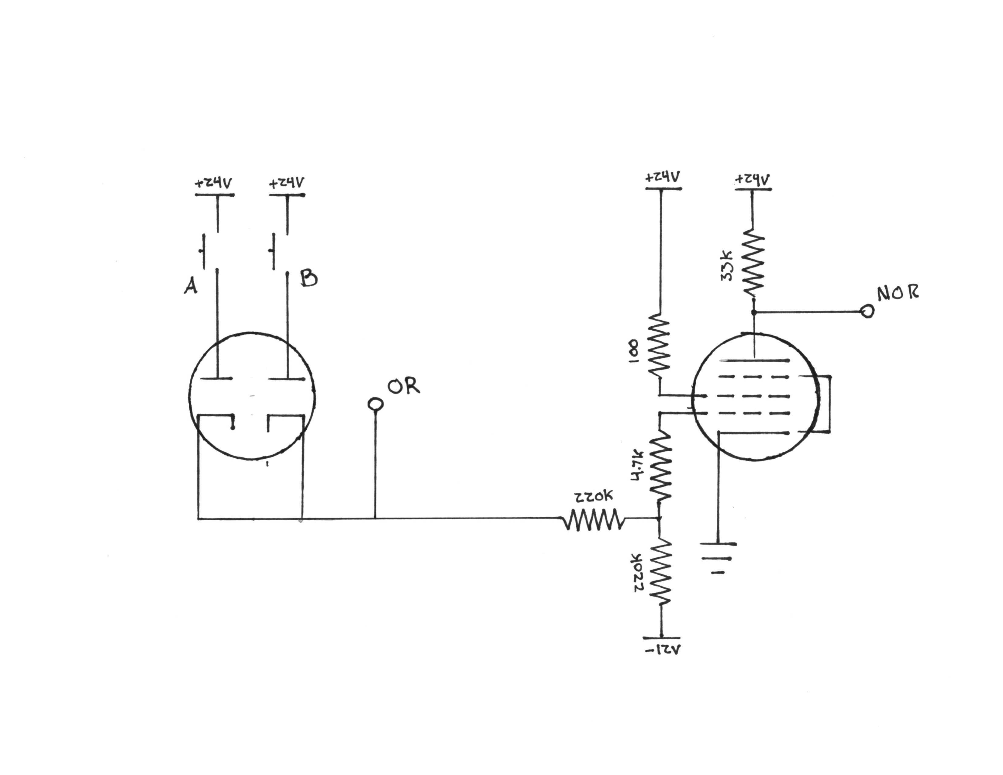
So, how do we make a NOR gate? Well, it’s just an OR gate with the output inverted, which means we can just stuff our inverter design on the end of an OR gate. How do we make an OR gate? That’s even easier, we just use two diodes!
The 6AU6 makes an excellent low voltage inverter, and if we pair this with a 6AL5 dual diode, we can get a perfect, all vacuum tube, low-voltage NOR gate.
But, as much as I love the idea of an all tube NOR gate, for the number of NOR gates required to actually make this thing work, the physical space requirements and filament power requirements would get a little intense. So, instead, let’s use two silicon diodes in place of the 6AL5.
But, that’s cheating!
Yes and no. Sure, it’s not a fully hollow state design, but vacuum tube computers often used silicon diodes in conjunction with tubes in the late 50s. The IBM 604, 650, 705, 750 and many other machines made use of silicon didoes in some fashion or another. The LGP-30 is perhaps my favorite example though, it used just 113 tubes and 1,450 silicon diodes, working primarily on diode logic.
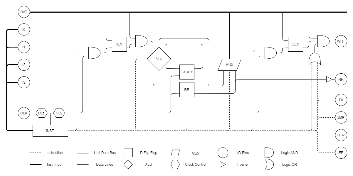
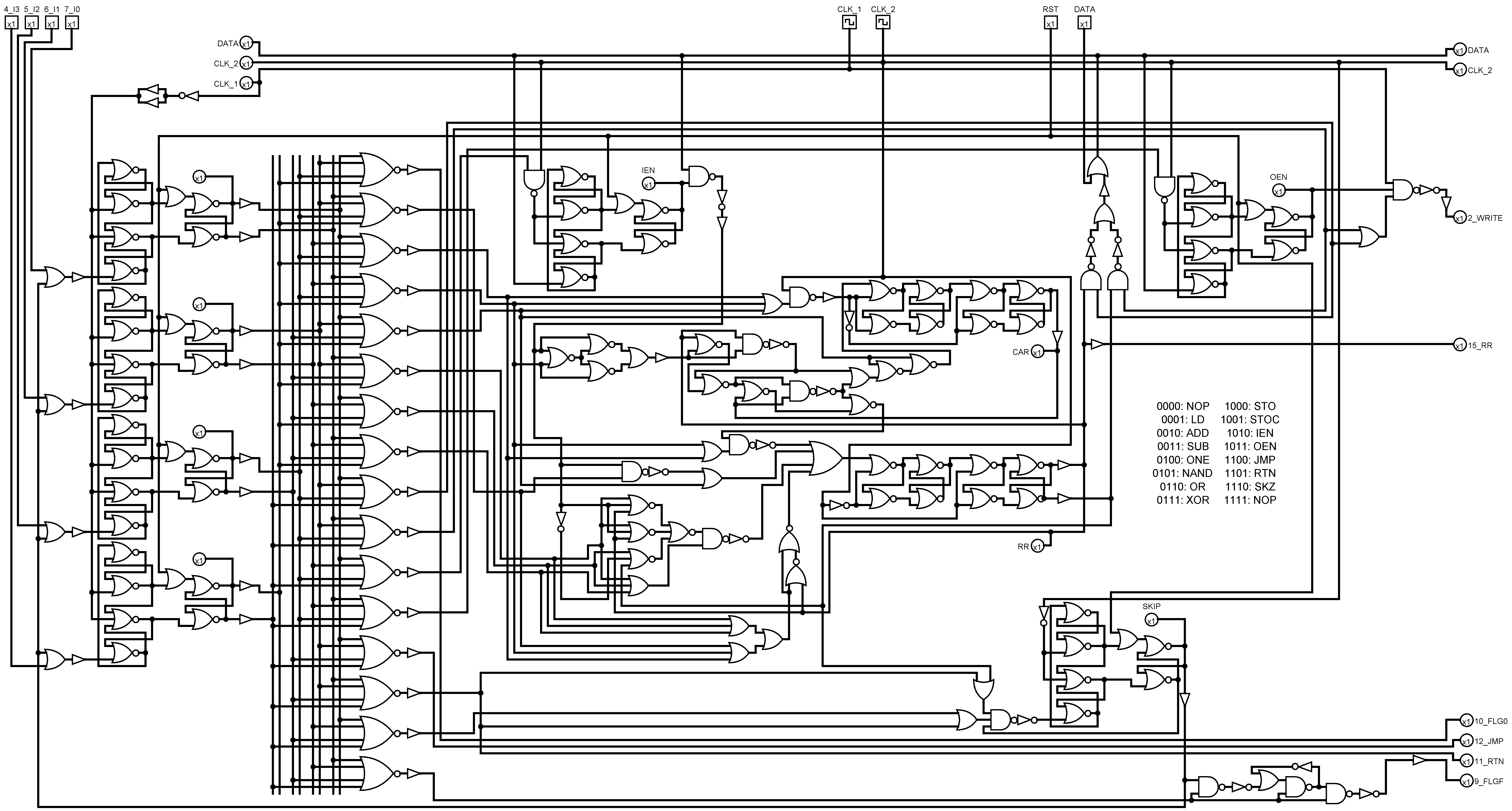
Now that we’ve got our NOR gate, it’s time to sit down and figure out how to build this entire thing out of just NOR gates! And this was the result:
We’ll dissect this in much more detail in the next log!
Thanks for reading!
After I had decided on an architecture that I liked, it was time to figure out just how to implement that architecture. But, before I could get that far, I needed to figure out some groundwork in just how to build the system.
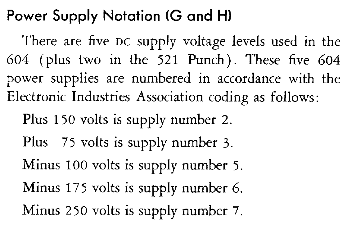
Traditionally, vacuum tube computers run at hundreds of volts and often use a massively wide variety of voltages. The IBM 604 Vacuum Tube computer uses +150V, +75V, -100V, -175V and -250V!
I'm a bit of a dolt though and tend to stick my fingers in the middle of circuits without really thinking. I wanted to avoid high voltages as much as possible on this build. So, I instead decided to use +24V and -12V. These specific voltages were chosen for two reasons.
First, they're super low and safe. Even at the greatest potential difference on the circuit, there is just 36V difference, which is about as harmless as it can get.
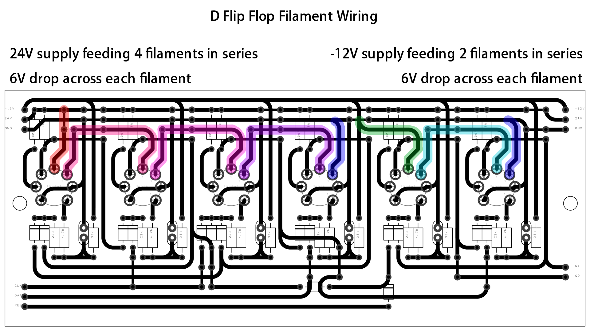
Second, it makes powering 6V heaters in series extremely easy. I can just build all my logic circuits around 2-tube or 4-tube modules and eliminate the need for a third, 6V power supply.
Here's one of my D flip flop designs. It uses 6 vacuum tubes in total. The first four tube heaters are in series and powered off the +24V supply, and the final two tube heaters are in series and powered off the -12V supply.
So, we've got our power supply squared away, but using tubes at low voltages is really unconventional and there's very little information out there about it. Most believe (initially myself included) that tubes can't operate at low voltages. However, the truth is, most tubes do pretty decently at low voltages, and there are even some tubes do really surprisingly well at low voltages.
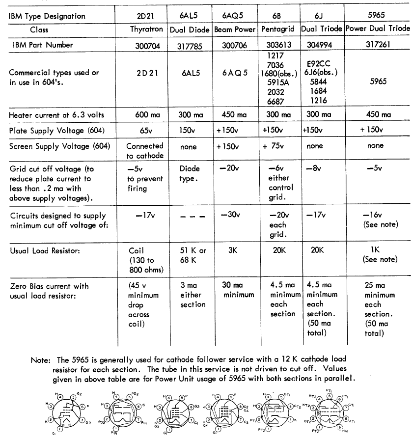
But, I'm not mega rich, so there is definitely a budget to consider here. Meaning, I need to find the best tube for low voltage that is also still affordable in large quantities. Looking at the IBM 604, they use a variety of tubes, which range from fairly common and affordable to relatively rare and expensive now:
The 6J6 7-pin dual triode seemed to be the tube that IBM liked to use for most of the logic circuits due to how compact it was. And, while they're still decently affordable today, in large quantities they can start to get really pricey. Furthermore, I had no idea how well they would perform at low voltages. The answer was to just do a whole lot of testing on a bunch of different tubes.
I ordered a couple random tube lots off of eBay that had a wide array of tubes (including the 6J6). But, now that I had the tubes, I had to figure out how to test them at low voltages. The IBM 604 built nearly everything out of one fundamental building block: the inverter.
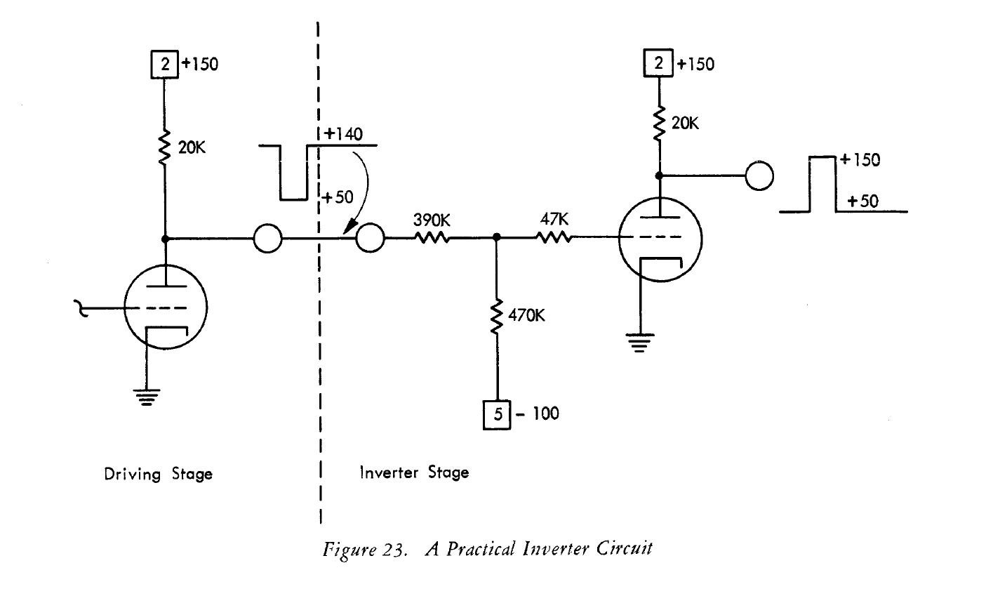
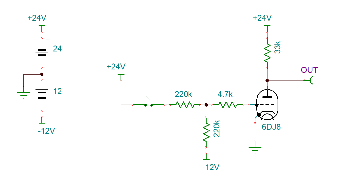
A large resistor on the plate, the cathode connected directly to ground, and a resistor divider on the grid biased to a negative voltage. So, all I needed to do was take this circuit and modify it work well at low voltages, and then test all my different types of tubes in that design to see how well they performed. Here's the inverter circuit I came up with that formed the very basis of everything I built:
You can see it's nearly identical to the IBM inverter. All I've changed are the resistor values and the supply voltages. Next, to do proper testing, instead of a switch as the input, I used a potentiometer so I could set the grid voltage at a specific level and measure the output voltage at the plate. After hours of testing, I came up with some pretty interesting results!
Pentodes:
Triodes:
As you can see, there's quite a large difference in behavior between pentodes and triodes. Pentodes tend to transition from cutoff (no electron flow) to saturation (max electron flow) very quickly, which is excellent for digital circuits. However, triodes have a much longer, more linear transition, which makes them excellent for audio use, but not ideal for computing use.
Now, IBM used the 6J6 dual triode tube, but they had a lot more voltage to work with, so I believe the longer transition was less of a worry. However, since I have so little voltage to work with, the faster...
Read more »The first step was coming up with an architecture that made sense. Initially, I was thinking to build a replica of the SAP-1 8-bit architecture using tubes, but that was going to require thousands of tubes and my wallet wasn't prepared for that much of an investment.
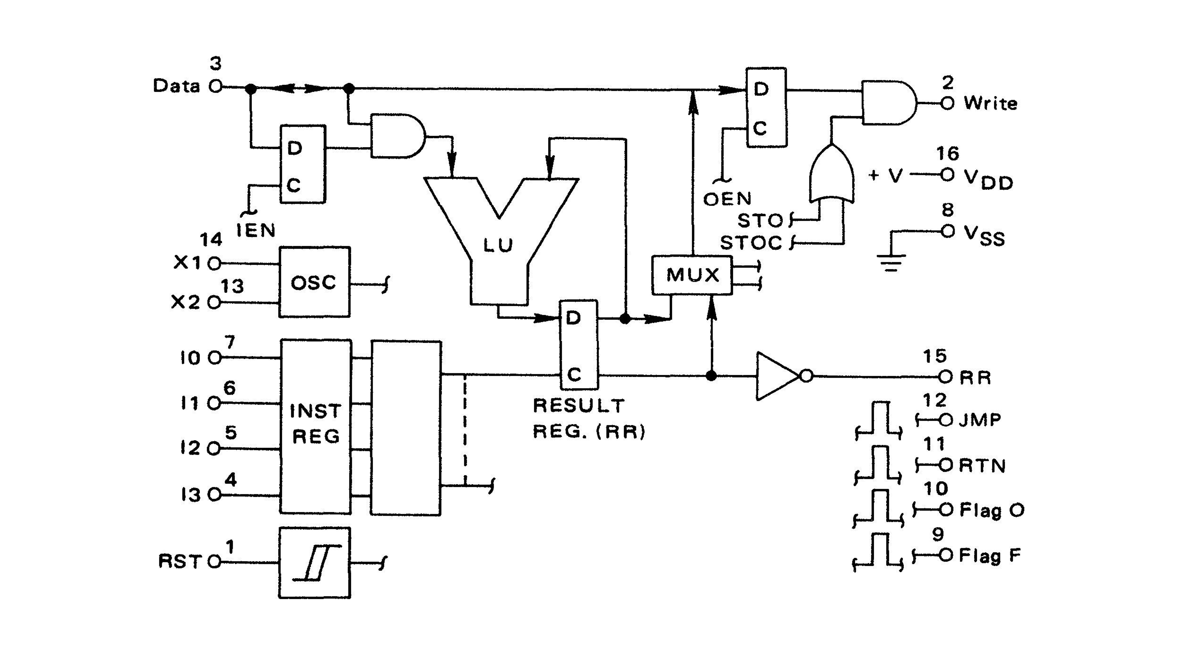
The answer came in the form of the MC14500 1-bit Industrial Control Unit, which is a very unique little 1-bit microprocessor. Here's the block diagram for it:
What I like best about this design is that it offloads memory and program control to other aspects, which means it has the flexibility to be used with any memory or program control design you want. That was particularly useful because I had no idea how I was going to go about implementing those aspects.
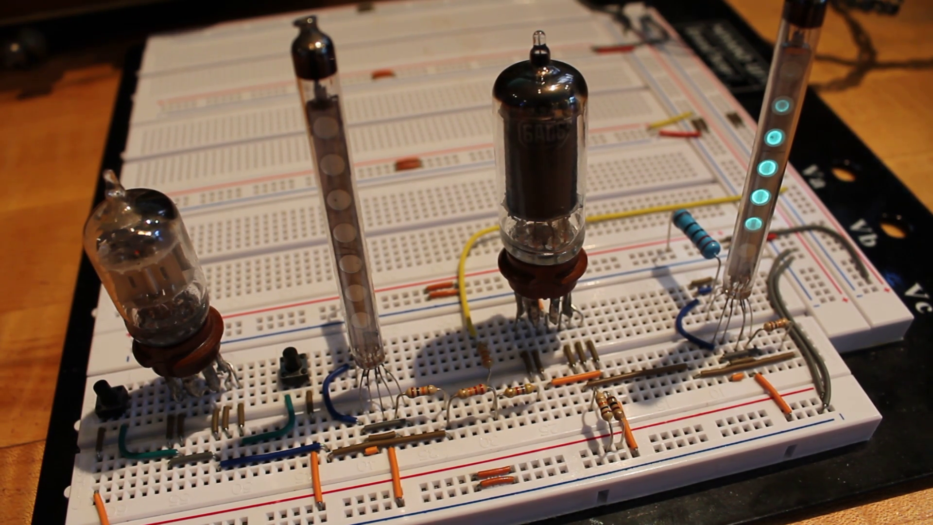
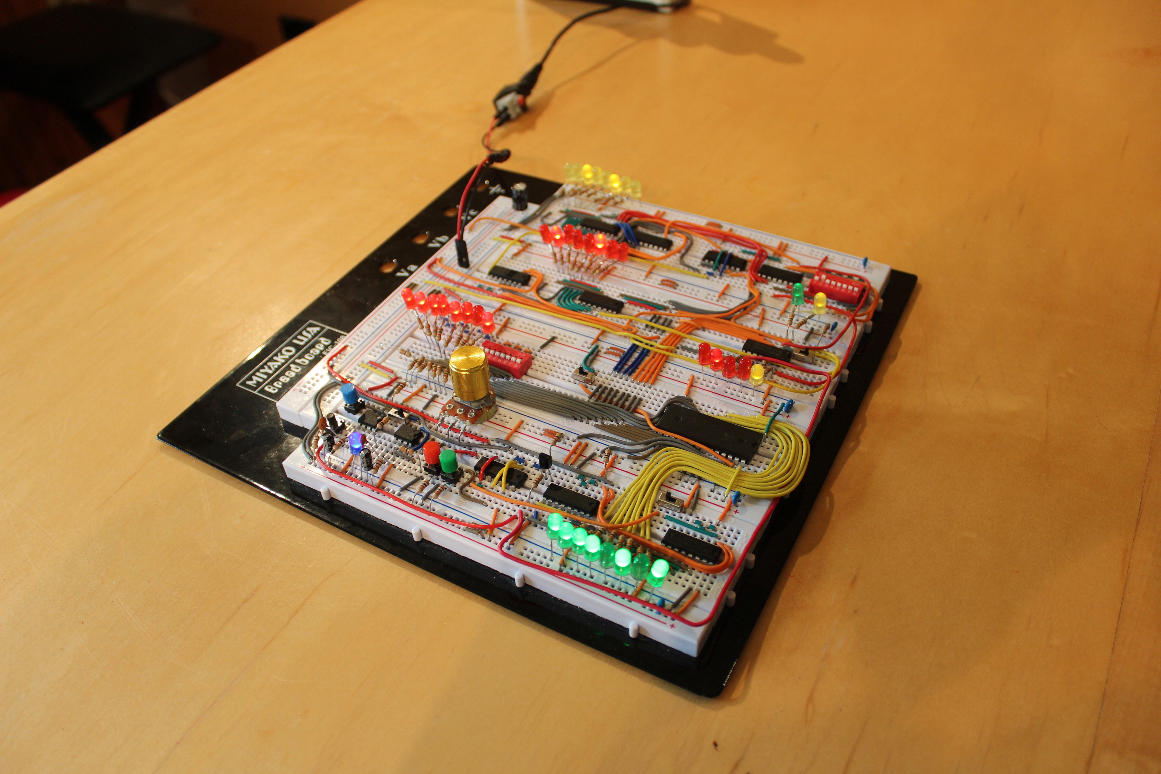
To make sure that this was going to work out well, I decided to build up a simplified IC computer of sorts based around this chip on the breadboard. The result was this very awesome looking collection:
This worked excellently and was a ton of fun to build, but had one major flaw. The Logic Unit was atrocious! In order to add two 1-bit numbers together took 12-steps. A simple 8-bit increment program had over 100 steps in it, which is ridiculous.
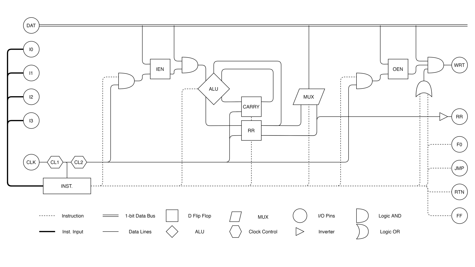
So, I got to work redesigning the LU into an ALU all while staying within the confines of the original architecture.
Originally, the LU had the following operations:
Load
Load Complement
OR
OR Complement
AND
AND Complement
XNOR
The new ALU has these operations:
Load
Addition
Subtraction
Force one
NAND
OR
XOR
The only operation that will be missed is the load complement, but the proper arithmetic operations will let me make up for it in other regards. I feel this is a much more capable design now! Here's the new block diagram:
That's it for this first build log!
I'll add more logs as I get more time!


 matseng
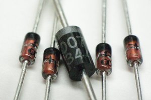
 Ted Yapo
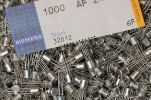
 Yann Guidon / YGDES
This project really gets my attention :-)