0%
0%
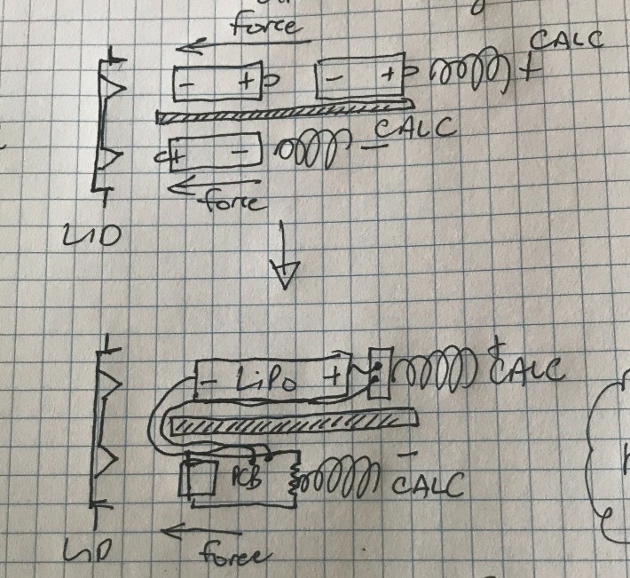
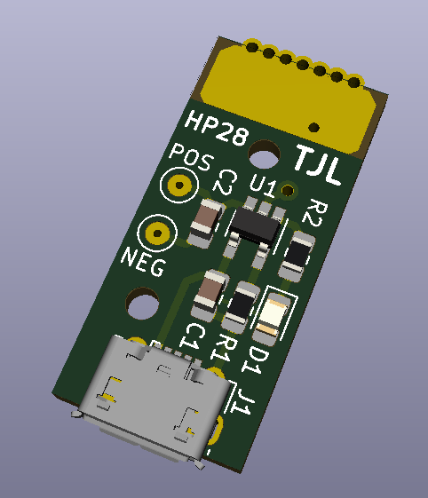
HP 28S LiPo Battery
My attempt at a non-destructive LiPo retrofit for the unique-yet-somewhat-loathed HP 28S calculator
 tomcircuit
Become a Hackaday.io member
Already have an account? Log in.
Just one more thing
To make the experience fit your profile, pick a username and tell us what interests you.
Pick an awesome username
hackaday.io/
Your profile's URL: hackaday.io/username. Max 25 alphanumeric characters.
Pick a few interests
Projects that share your interests
People that share your interests


 UltraReidar
 makeTVee
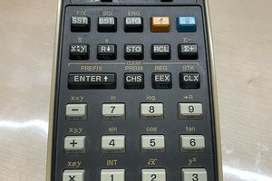
 CYUL
CYUL
I’ve been running the “repeating self-test” to see how long a charge lasts. So far more than 48 hrs, but I have no idea how long the same test can run on a fresh set of N cells.
Anyone ever done this, by chance? I can access the positive and negative terminals in my 28S and do the N cell test after the LiPo discharges. But I have no idea how long that will be…