Close
0%
0%

OmniRotor: An Agile, Coaxial, All-Terrain Vehicle

A coaxial, versatile, modular, tilt-rotor, all-terrain vehicle that can apply its full thrust in any direction.

Public Chat
Similar projects worth following
A coaxial, versatile, modular, tilt-rotor, all-terrain vehicle that can apply its full thrust in any direction. The OmniRotor platform can be used for search and rescue, environmental monitoring, infrastructure inspection, and aerial manipulation applications. More information can be found at the following videos:

Agile, co-axial, omnidirectional rotor module: https://www.youtube.com/watch?v=1dOp-dNc0_U
Omnirotor, all-terrain platform: https://www.youtube.com/watch?v=JN7Ji_fr_0w

OmniRotor GitHub page: https://github.com/newdexterity/OmniRotor
Coaxial benchmarking platform GitHub page: https://github.com/newdexterity/Coaxial-Benchmarking-Platform
Omnirotor Firmware: https://github.com/JBuzzatto/Omnirotor_Firmware

This work is licensed under a Creative Commons Attribution-ShareAlike 4.0 International License.

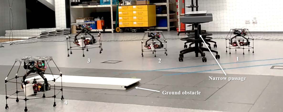
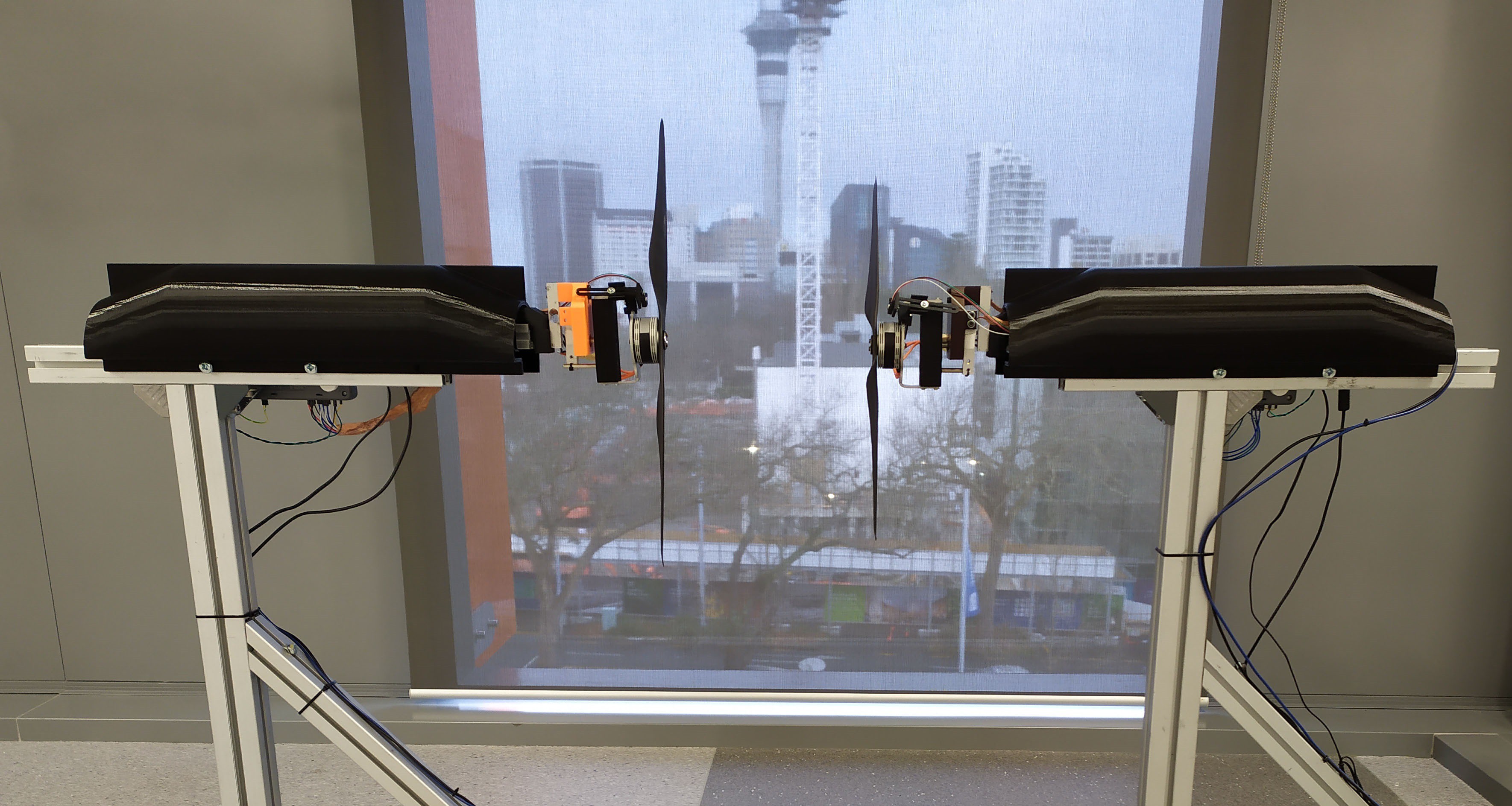
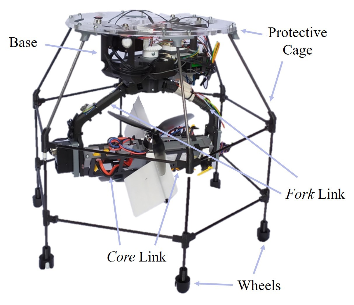
Micro Aerial Vehicles (MAV) with Vertical Takeoff and Landing (VTOL) capabilities, such as quadrotors, have offered significant value to many research fields and markets. However, only recently, MAV began to be explored as systems capable of interacting with the environment, performing manipulation tasks, and participating in more versatility-demanding operations. Pursuing the goal of turning flying machines into more versatile instruments, many researchers have resorted to using tilting rotor mechanisms to create new aerial vehicle concepts. Nevertheless, most such new concepts are bulky and lack the required versatility, and are restricted to particular applications. In this work, we address these issues by proposing a novel coaxial, versatile, modular tilt-rotor, all-terrain vehicle concept.


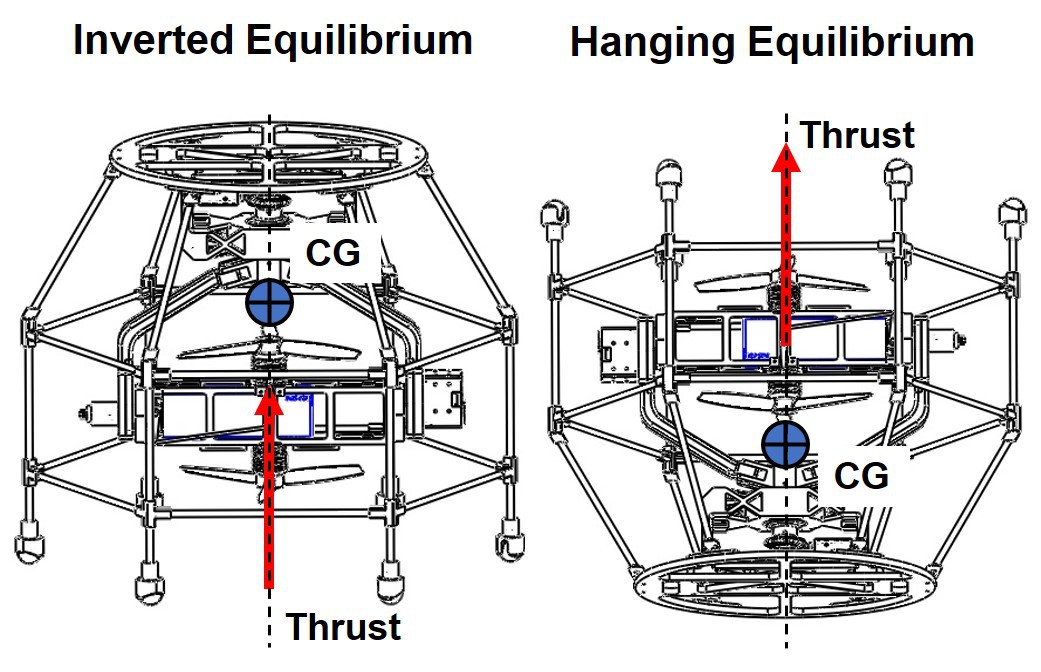
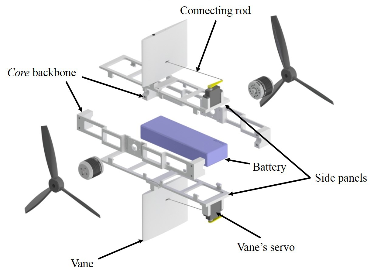
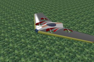
The OmniRotor platform can apply its full thrust in any direction, regardless of the frame's orientation where it is mounted. The platform does not have any limitations regarding rotation's range. It can change its thrust direction continuously without needing to unwind back to a specific configuration. With the addition of control surfaces between the coaxial rotors, the OmniRotor is turned into a functional VTOL MAV with hovering capabilities that can be used as a ground vehicle, a UAV, and an all-terrain vehicle.

The OmniRotor can be used for search and rescue, environmental monitoring, infrastructure inspection, and aerial manipulation applications. 

BOM Omnirotor v2.xlsx

Bill of Material for the Omnirotor.

sheet - 12.72 kB - 10/24/2021 at 23:40

Download

Coaxial Benchmarking Platform - BOM.xlsx

Bill of materials of the coaxial benchmarking platform that we are using for modelling purposes.

sheet - 10.09 kB - 10/24/2021 at 22:03

Download

OmniRotorV2_CAD.zip

Cad files of individual components for the Omnirotor vehicle, version 2.

x-zip-compressed - 18.29 MB - 10/24/2021 at 21:22

Download

OmnirotorV2.STEP

Step file of the full assembly for the Omnirotor vehicle, version 2.

step - 17.16 MB - 10/24/2021 at 21:21

Download

Coaxial Benchmarking Platform - CAD.zip

CAD files of the coaxial benchmarking platform.

x-zip-compressed - 2.12 MB - 10/05/2021 at 20:22

Download

View all 6 files

View all 20 components

  • Some Results of Coaxial Rotor Experiments on the Benchmarking Platform

    Joao Buzzatto10/19/2021 at 20:15 0 comments

    Three sets of rotors are used here. The main difference between the rotors is their KV and the recommended propeller size. Table I summarizes the components comprising the rotors sets and the testing conditions. The coaxial system experiments consist of swiping each motor's commands from 7% to 95%, divided into 10 equally spaced points, resulting in a total of 100 data points per test. With such tests, we obtain a map for the coaxial system that practically covers the whole actuation space of the rotor pair. 


    We investigate how the map characteristics (especially efficiency) changes when varying the separation distance between the rotors. Since the tests consider three different rotor sizes, the spacing between the rotors is specified as the non-dimensional ratio z/D, where z is the distance between the propellers and D is the propeller diameter. The same set of ratios is tested for the three rotor sets. The values range from 0.1 to 1 divided into 7 equally spaced points, as displayed in Table II. The range selected is considered by the authors to be a reasonable one found on most multirotor vehicles having coaxial rotors as propulsion units and being constructed of common, off-the-shelf components.

    Fig. 1: Plots of mechanical and electrical efficiencies against thrust for all coaxial rotor sets tested at z/D = 0.7. Efficiency measurements plotted against thrust for the whole actuation domain create areas with clear upper boundaries. The results indicate that for every desired thrust, there is a corresponding maximum efficiency operating point. Additionally, highlighted in black are the points of equal commands. For most of the thrust range, such points are below the maximum efficiency boundary.

    For each rotor set, testing across all separation ratios results is 700 data points in total, where each data point has individual rotor information about the command sent, thrust, torque, voltage, current, and rotation speed. Presenting all the data in this document is impossible, thus we focus on discussing the most interesting results for all rotor sets across all distances.


    As expected, for a coaxial system, the relationship between thrust and mechanical and electrical efficiencies is not one to one, and the result is not a clear curve. Instead, the result is an area (see Fig. 1). However, the more interesting observation is that the area formed by plotting mechanical or electrical efficiency against thrust has a clear upper boundary covering the whole thrust range for the coaxial system. This indicates that every thrust along this range has a correspondent operating point on the maximum efficiency boundary. Moreover, when highlighting the points corresponding to equal commands sent to both rotors, the curve it forms is below the curve formed by the upper boundary. This is observed for most of the system's thrust range and for both mechanical and electrical efficiencies. Furthermore, the same is true not only for the results shown in Fig. 1 but for all of the experiments considered here. Therefore, based on the experiments presented, we can summarize two main observations: i) for a coaxial system comprising equal, counter-rotating electric rotors with propellers of fixed pitch, powered with the same source, there is a boundary of maximum efficiency that covers the whole thrust range and ii) the condition of equal commands for both rotors is below the maximum efficiency boundary for most of the system thrust range.

    Fig. 2: Mechanical and electrical efficiencies variation across rotor distances. The plots show the results for two cases, the maximum efficiency set, and equal commands. The first two columns of plots show the results for the rotors with 22 inches propellers. The 16.2 inches rotors results are displayed in the third and fourth columns, while the results for the 11 inches rotors are in the last two columns.

    Given the observations above, the next step is to investigate how the two relevant conditions behave...

    Read more »

  • Design of the Benchmarking Platform for Coaxial Rotors

    Joao Buzzatto10/17/2021 at 18:52 0 comments

    Fig. 1: The benchmarking platform designed to test coaxial rotors systems used on multirotor UAVs. Each side of the testing rig is equipped with force and torque sensors for measurements on one axis. Individual motor speed, applied voltage, and consumed electric current are also measured. Everything is integrated and controlled by a LabView interface, where both closed and open-loop experiments can be programmed.

    The platform structure is made out of modular aluminum extrusions. It comprises two identical units placed one in front of the other. Such units are perfectly aligned with the help of another long, continuous extrusion that holds the whole structure together. The design assumes that the propellers are mounted so as to generate forces only in one direction (i. e., pushing from left to right on Fig. 1), where the structure is reinforced with 45 degrees bars. The final extrusion placed on the top-most part of each stand unit holds all the sensors and the electronics.  Such placing of components allows for easy and fast reconfiguration of the benchmarking platform. To change the distance between the rotors, one needs only to untighten two screws from each side and to slide the extrusions to another position. Additionally, a black 3D printed case was placed over each stand unit to protect and cover the sensitive electronics and wires that connect all sensors and controls.

    The coaxial system's quantities of particular interest for us are the induced thrust, torque, motor speed, applied voltage, and electric current consumed by each rotor. By measuring such quantities, it is possible to obtain the total induced thrust, torque, electrical and mechanical power and efficiency of the whole coaxial system for any configuration tested. Fig. 2 illustrates the setup designed to acquire such information from a coaxial rotor system. 

    Fig. 2: Diagram illustrating the components of a unit of the benchmarking platform. The platform is controlled with a LabView interface. On each side, all sensors are connected to a National Instruments MyRIO device. Both units of the platform are connected to a single PC and power supply.

    Every sensor on the platform is integrated into a LabView interface. The computer running the LabView program communicates with a National Instruments MyRIO development device. The MyRIO is the hardware interface that collects data from all sensors and sends commands to control the motors. The force and torque measurements are taken with the use of appropriate load cells. The signal from the load cells is first amplified and converted to digital information by using HX711 breakout boards. The digital data is then collected by the MyRIO unit (Fig. 2). Rotational speed from the motors is measured by employing a long-distance reflective switch (OPB732WZ from TT Electronics) and reflective tapes placed on the motors. FPGA and real-time software embedded on the MyRIO makes sure that each pulse from the reflective switch is read, resulting in accurate speed measurements. Current is measured with the help of a SEN-16408 KR Sense Current Sensor, placed in series with the Electronic Speed Controller (ESC) and the power supply. To measure voltage, we employed a voltage divider connected directly to one of the AD ports on the MyRIO. Finally, PWM signals from the MyRIO are sent to the ESC to control the motors. Note that Fig. 2 shows the system for only one of the platform's units. In the image, the dashed lines coming out from the right side of the power supply and the computer running LabView indicate that the complete system continues with the same components on the other side, with the exception of the computer and the power supply. 

    As indicated previously, only two load cells are used to measure thrust and torque from the motor, as shown in Fig. 3. At one end, the thrust and torque load cells are mounted on the same part. The other end of the thrust load cell is mounted on the platform's structure, while...

    Read more »

  • An Open-Source Benchmarking Platform for Coaxial Rotor Systems

    Joao Buzzatto10/16/2021 at 20:23 0 comments

    Small scale, electric, Vertical Take-Off and Landing (VTOL) Unmanned Aerial Vehicles (UAVs) have been extremely popular in robotics, and roboticists prefer such vehicles because they integrate sophisticated small electric sensors, complex control algorithms, and they are mostly aimed at autonomous systems applications. UAV concepts have also grown in variety and complexity, both in terms of design and automation, but also aerodynamically. Aerodynamics research, however, is not the focus of the robotics community. So complex aerodynamic systems are usually treated in a simplified manner, often operating in sub-optimal conditions and not enough research effort is put towards improving them. This is particularly evident in multirotor vehicles with coaxial rotors, where each motor/propeller pair is still treated as a single rotor (as in the PX4 and ArduPilot flight stacks, for example). Such rotor configurations is generally used in applications requiring high thrust but small vehicle footprint, such as in aerial manipulation, drone delivery, and to enable the development of new vehicle concepts, such as the Omnirotor presented in this project. Due to their heavy load capacity and rotor redundancy, coaxial multirotor systems are also employed in manned multirotor and transport applications  (see EHang, Airspeeder, and DCL's Big Drone), or even for the exploration of Saturn’s moon Titan. But despite the large range of applications and the potential of coaxial rotor systems, there are very few works that focus on studying them and on how to improve them.

    Figure 1: The benchmarking platform designed to test coaxial rotors systems used on multirotor UAVs. Each side of the testing rig is equipped with force and torque sensors for measurements on one axis. Individual motor speed, applied voltage, and consumed electric current are also measured. Everything is integrated and controlled by a LabView interface, where both closed and open-loop experiments can be programmed.

    As part of the Omnirotor project, we also developed an open-source benchmarking platform for coaxial rotor systems that allows us to analyse and improve their efficiency. The platform is highly automated and allows for fast, extensive experiments measuring thrust, torque, motor speed, applied voltage, and electric current consumed by each rotor. Further details will follow on the next logs.

  • Experimental Validation of All-Terrain Navigation Capabilities

    Joao Buzzatto10/14/2021 at 08:03 0 comments

    To further validate the platform's practical feasibility experimentally, and assess its performance, the hybrid vehicle prototype was subjected to two tests. The first experiment demonstrates the concept's capabilities as an aerial vehicle. The prototype was required to start from rest, take off, and then track some desired path, maintaining a fixed heading orientation. Specifically, the path used forms an inclined eight shape in 3D space. The second test was designed to demonstrate the concept's capabilities as a UAV and a ground vehicle. On it, the prototype performs an emulated search-and-rescue scenario.

    The PX4 open-source flight stack of a Pixracer, a flight controller board commonly used for small racing quadrotors, was modified to incorporate the control strategy and inverse kinematics described in the previous section. The original attitude/rate controllers and mixer were adequately modified, while the middleware and other essential parts of the flight stack were kept, e.g., position controller, land/takeoff detector,  real-time task scheduling, and drivers for embedded sensors. The controller's output commands were mapped to the external actuators, i.e., Dynamixel servo motors, by creating an interface to the flight controller using the MAVLink messaging protocol and an OpenCM/Arduino board. The two 2050Kv brushless motors with 7-inch propellers were controlled directly by the flight controller and 4-in-1 ESC. Furthermore, MATLAB/Simulink running on an offboard PC was employed for handling telemetry, parsing and creating MAVLink messages, and transmitting position and orientation data as UDP packets to the flight controller. Pose measurements were obtained using a Vicon motion capture system.

    The desired orientation is set to a fixed value of 90 degrees. That orientation was precisely maintained with 1.3 degrees RMS error. Overall, the results are promising and validate the vehicle's ability to track complex 3D paths with satisfactory performance. However, such faults observed in the performance can not be overlooked. Some possibilities could explain the undesired behaviours the system displayed. The vanes' model between counter-rotating coaxial rotors is unknown, and the authors believe that once a model is obtained, control could be improved considerably. Furthermore, a design iteration that favors better rigidity, employing higher-end materials such as carbon fiber instead of PLA for some parts of the design, would reduce low-frequency vibrations and improve sensor readings. The considerable weight present in the Core link can also influence performance by transferring reaction torques due to its movement, disturbing the system. Such an effect could be reduced by increasing the distance between the CG and the thrust's application point with design changes. This would increase the attitude control authority, minimizing the impact of disturbances. Nevertheless, the prototype proved to be consistent in its flight performance and capable of tracking many other trajectories shapes, which are not presented here.

    Finally, to illustrate the Omnirotor platform's use as a hybrid vehicle, the concept was tested on a potential search-and-rescue environment. In the first part of this scenario, the vehicle transverses a track on the ground, starting from rest and crossing below a narrow, near-the-floor passage. This part of the experiment is performed with teleoperation, where a pilot controls the vehicle driving on the ground. The inputs from the pilot to the system are sent with a regular radio controller. To generate enough effort to move on the ground, the pilot commands low throttle values but large values of pitch and row. In this mode, the same control mapping and mixer used for flying are employed.

    In the second part of the scenario, while traversing the track through the soil, the vehicle is faced with an obstacle it supposedly can not cross as a ground vehicle. The Omnirotor then changes mode switching...

    Read more »

  • Control Surfaces in Between Coaxial Rotors

    Joao Buzzatto10/05/2021 at 05:42 0 comments

    A drawback of the gimbal mechanism is its kinematic singularities points. These are points in its workspace where, when performing inverse kinematics to track a path, minimal changes on its pointing direction results in large motion of the joints. This results in the rotor-on-gimbal mechanism's inability to perform small force corrections quickly without introducing disturbances to the system when operating near such singularity points. Unfortunately, in the proposed all-terrain vehicle concept, which utilizes only one of the rotor-on-gimbal module, the Center of Gravity (CG) of the system is always aligned with the kinematic singularity for both of its stable configurations (see Fig. 1).

    Fig. 1: Illustration of the two possible hovering stable points for the all-terrain vehicle concept with one rotor-on-gimbal module. For the vehicle to hover stably, the vehicle's weight must be aligned with the thrust produced by the rotor. This happens when the CG is either above the rotors (inverted equilibrium) or below it (hanging equilibrium). Such direction coincides with the gimbal kinematic singularity, which is aligned with the axis of the first joint.

    A possible solution to such a problem is to add control surfaces downstream to the propellers, arranged perpendicular to the second DoF. Such addition provides enough control authority in all directions even when operating at the gimbal's singularity points. However, given the limited space to fit such addition and to keep a small footprint for the rotor-on-gimbal design, it was decided to place the control surfaces between the coaxial rotors, as shown below (Fig. 2). Despite the considerable added complexity to the system, especially in the aerodynamics sense, this solution approach is lightweight, easy to incorporate, and inexpensive.

    Fig. 2: Exploded view of the Omnirotor central module. This `Core' part includes several critical components of the design. More precisely, it consists of the battery, the rotors, and the control vanes. The backbone of the module has two attachment points for the rotors. The side panels hold both the control vanes and the servos that actuate them. The side panels and the backbone structure were designed to lock the battery inside and provide rigidity to the assembly.

    For the prototype, two 9 g HD-1900A micro servos actuate the control surfaces. They are mounted to 3D-printed PLA holders, which are glued to the battery case lids. The control surfaces, or vanes, are 3D-printed PLA NACA 0006 airfoil profiles, with 100 mm chord length and 90 mm spam. These vanes hinge about 4 mm carbon fiber rods, which are press-fitted into 3D-printed PLA holders glued to the battery case lids. The servo horns and the vanes are connected by 0.8 mm steel rods, and together they form a parallel four-bar linkage. Such parallel linkage arrangement guarantees that the motion of the control surfaces is equal to the servos' motion but translated by their separation distance.

    As mentioned before, when the vehicle is at hovering its CG is aligned with the gimbal's kinematic singularity. To control the UAV in this operating point, we maintain the first DoF locked, and the vanes movement coordination performs compensations on the pitch axis. An important note here is that the control of the vanes is not based on a model. In contrast to the well-known and studied rotor typical on multirotor UAVs, at the time of writing, the authors could not find in the literature any study which describes the system used here, i. e., a counter-rotating coaxial rotor system with control surfaces placed in between them.

    Implementation-wise,  control of the vanes is done by the use of a properly set mixer on the flight controller. Given that each vane is controlled by an independent servo motor, here we consider that they can contribute to the regulation of the system in two ways: i) Help to regulate yaw, and ii) control the vehicle's pitch. To control yaw, the mixer sends commands to...

    Read more »

  • Designing an all-terrain, hybrid vehicle

    Joao Buzzatto10/05/2021 at 05:13 0 comments

    With the proposed rotor-on-gimbal design, the system's increased capability leads to a variety of applications. Given the ability to apply thrust in any direction without being limited by the base mount's orientation, one possible application is to place this modular rotor concept on a structure with wheels. The result is a vehicle able to roll on the ground and fly, acting both as a ground robot and an Unmanned Aerial Vehicle (UAV).

    With the flexibility of the omnidirectional thrust vectoring, the system can easily overcome obstacles by taking-off the ground. Furthermore, having the base mount attached above the rotor module, i. e., in an upside-down manner, brings the center of gravity of the system closer to the ground. This reduces the torque the rotor's thrust generates when the wheels are in contact with the ground, making it stable for operation as an Unmanned Ground Vehicle (AGV). Carbon fibre rods form a hexagon structure connected with 3D-printed PLA connectors. The use of carbon fiber rods ensures that the frame will have adequate strength without a significant increase in the overall weight of the UAV. This structure is connected to a laser-cut acrylics sheet mount, where the rotor module base is attached. The carbon fibre structure is fitted with a lightweight (7 g) injected-molded, Pololu ball caster with 3/4 inches Plastic Ball. With electronics and propellers inside the cage-like structure, the impact of collision incurred damages to the UAV, is minimized.

    Demonstration Video 1: https://www.youtube.com/watch?v=1dOp-dNc0_U
    Demonstration Video 2: https://www.youtube.com/watch?v=JN7Ji_fr_0w


  • The Rotor-On-Gimbal Mechanism

    Joao Buzzatto10/05/2021 at 04:17 0 comments

    Given the aim of developing a rotor module capable of applying its full thrust in any direction, the more obvious solution is to place the rotors on a structure that rotates according to two perpendicular joints. Such a mechanism is called a gimbal, and it is largely employed in camera systems. The immediate limitation that arises from such an approach, however, is the wiring. Every active rotor tilting mechanism is limited to turn by how much its wire connections can wind around the rotating axis. The standard solution for these wiring constraints is solved by employing slip-rings, which are essentially rotary electric connections. Once again, this is common on gimbal camera stabilization systems. However, brushless electric motors used for propulsion systems tend to draw large amounts of electric current, leading to large and heavy slip-rings. This extra weight is undesirable and would limit the flight time and payload capacity of the vehicle considerably.

    To avoid using two heavy slip-rings on the two DoF gimbal mechanism, we proposed the solution of changing the location of the electric components on the system circuit. Instead of placing the battery away from the rotors and at the geometric center of the UAV, as it is commonly done for most multirotor UAVs, the proposed solution places the battery together with rotors. This approach shortens the wire length for the power connections (mainly from the battery to the ESCs and rotors), leaving only low current wire connections routing toward the vehicle's base and the control boards. By employing the slip-rings in this configuration, the proposed design can use both DoF continuously. This means that the base's orientation does not affect the direction to which the thrust is applied. Additionally, by placing the battery with its wider side along the rotors' axis, the propellers' occlusion effect is minimized. In our design, the dimension of this occlusion is only slightly wider than the motors' diameter.

View all 7 project logs

Enjoy this project?

Share

Discussions

rraetz wrote 10/20/2021 at 08:23 point

Amazing project! What flight control firmware are you using? PX4, Ardupilot?

  Are you sure? yes | no

Joao Buzzatto wrote 10/20/2021 at 18:59 point

Thank you! We appreciate it! We use PX4 on the OmniRotor, with some modifications to the stack to support the new frame. We intend to open source the modifications soon.

  Are you sure? yes | no

Similar Projects

Does this project spark your interest?

Become a member to follow this project and never miss any updates