 Joao Buzzatto
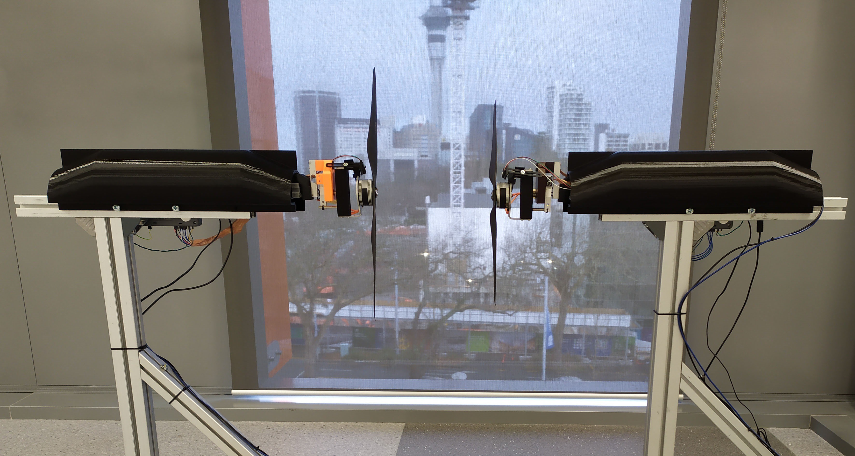
The platform structure is made out of modular aluminum extrusions. It comprises two identical units placed one in front of the other. Such units are perfectly aligned with the help of another long, continuous extrusion that holds the whole structure together. The design assumes that the propellers are mounted so as to generate forces only in one direction (i. e., pushing from left to right on Fig. 1), where the structure is reinforced with 45 degrees bars. The final extrusion placed on the top-most part of each stand unit holds all the sensors and the electronics. Such placing of components allows for easy and fast reconfiguration of the benchmarking platform. To change the distance between the rotors, one needs only to untighten two screws from each side and to slide the extrusions to another position. Additionally, a black 3D printed case was placed over each stand unit to protect and cover the sensitive electronics and wires that connect all sensors and controls.
The coaxial system's quantities of particular interest for us are the induced thrust, torque, motor speed, applied voltage, and electric current consumed by each rotor. By measuring such quantities, it is possible to obtain the total induced thrust, torque, electrical and mechanical power and efficiency of the whole coaxial system for any configuration tested. Fig. 2 illustrates the setup designed to acquire such information from a coaxial rotor system.
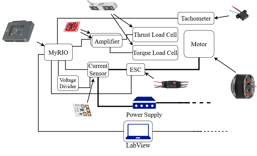
Every sensor on the platform is integrated into a LabView interface. The computer running the LabView program communicates with a National Instruments MyRIO development device. The MyRIO is the hardware interface that collects data from all sensors and sends commands to control the motors. The force and torque measurements are taken with the use of appropriate load cells. The signal from the load cells is first amplified and converted to digital information by using HX711 breakout boards. The digital data is then collected by the MyRIO unit (Fig. 2). Rotational speed from the motors is measured by employing a long-distance reflective switch (OPB732WZ from TT Electronics) and reflective tapes placed on the motors. FPGA and real-time software embedded on the MyRIO makes sure that each pulse from the reflective switch is read, resulting in accurate speed measurements. Current is measured with the help of a SEN-16408 KR Sense Current Sensor, placed in series with the Electronic Speed Controller (ESC) and the power supply. To measure voltage, we employed a voltage divider connected directly to one of the AD ports on the MyRIO. Finally, PWM signals from the MyRIO are sent to the ESC to control the motors. Note that Fig. 2 shows the system for only one of the platform's units. In the image, the dashed lines coming out from the right side of the power supply and the computer running LabView indicate that the complete system continues with the same components on the other side, with the exception of the computer and the power supply.
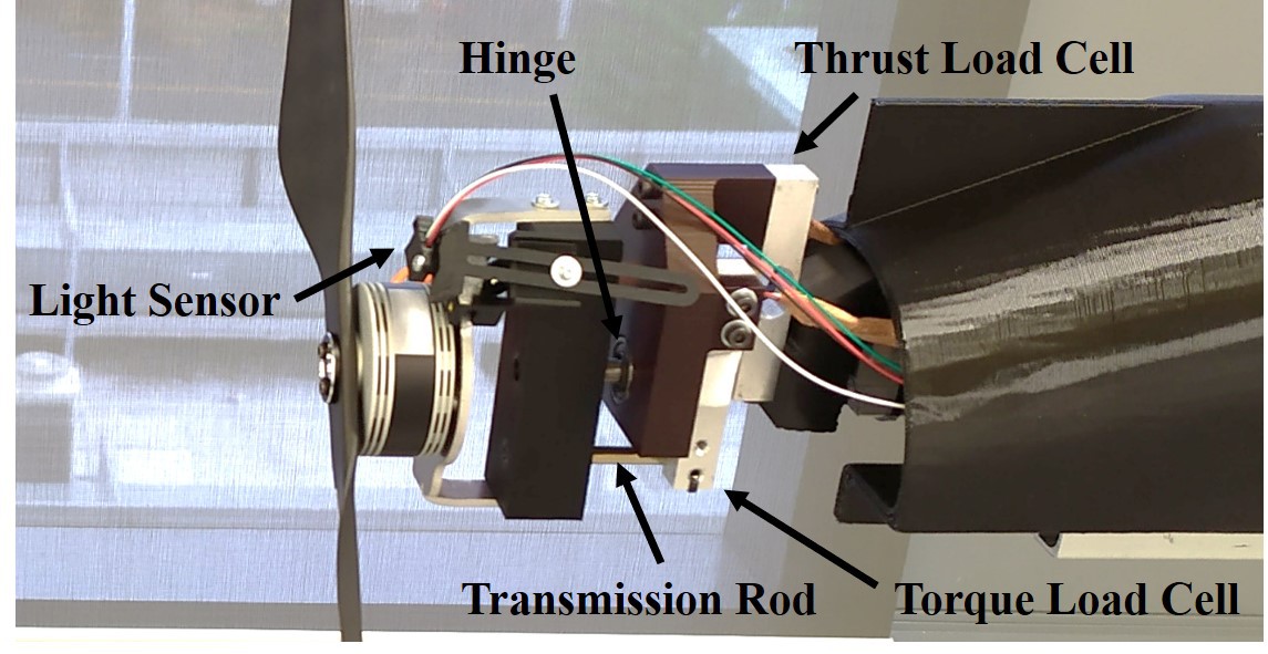
As indicated previously, only two load cells are used to measure thrust and torque from the motor, as shown in Fig. 3. At one end, the thrust and torque load cells are mounted on the same part. The other end of the thrust load cell is mounted on the platform's structure, while the other end of the torque load cell is not rigidly mounted on any other structure. Instead, torque is measured by sensing the force a transmission rod exerts on the load cell. Such rod is attached to a part that is free to rotate with respect to the part where both load cells are mounted, and the only resistance to such rotation is provided by the contact of the rod with the torque load cell.
However, to prevent the rod part and the rotor mounted on it from rotating in the other direction, the rod is fixed in contact with the load cell. This sensor design assumes that torque will be applied in only one orientation. Measurements for torques applied with the opposite of the designated rotation direction are not as precise. Therefore, they are avoided on all tests performed on this work by keeping the rotors rotating in the proper direction only. Finally, an aluminum plate cut with a water-jet cutting machine provides support where the motor is mounted. The plate has 90 degrees bent ends and is attached to the part containing the rod. Using 5 kg rated load cells, each stand unit is estimated to measure thrusts of up to 5 kgf with precision of 2.5 g, and torques of up to 1.4715 Nm with precision of 0.00073575 Nm, with minimal cross talk.
Discussions
Become a Hackaday.io Member
Create an account to leave a comment. Already have an account? Log In.