Close
0%
0%

Spot Welder

Custom Spot Welder machine based on MOT

Similar projects worth following
The motivation to build this project was to design a custom battery for my electric scooter. (Increase the horse-power, yeah :) .)

- One way was to take a look on the aliexpress/eBay and buy some parts. But when I looked at the portfolio, all devices had some minuses. (To be honest, I don't want to buy 2-3 devices and put them together into one ... .) Of course, there are some usable. On the other hand, if we look at the price, those are unusable, especially because of weight => cost for postage.
- Second way, create something, what will be usable for my application.

So, the decision was... DIY :).

After some time I decided to present some of my last custom made device, the Spot Welder. Maybe there is nothing special to present, but I will try to describe it anyway.

Device is used for spot welding batteries and made some accu-packs from them.

Features:
- custom handle
- pre-welding
- pulse/pulse mode
- simple user-interface

I used 1kW MOT (Microwave transformer) as a power source. (It was really a problem to find such a device with 800W power at least.) The MOT is switched by optocoupler + triac. There is nothing special behind, just a triac regulation, or better triac switching.

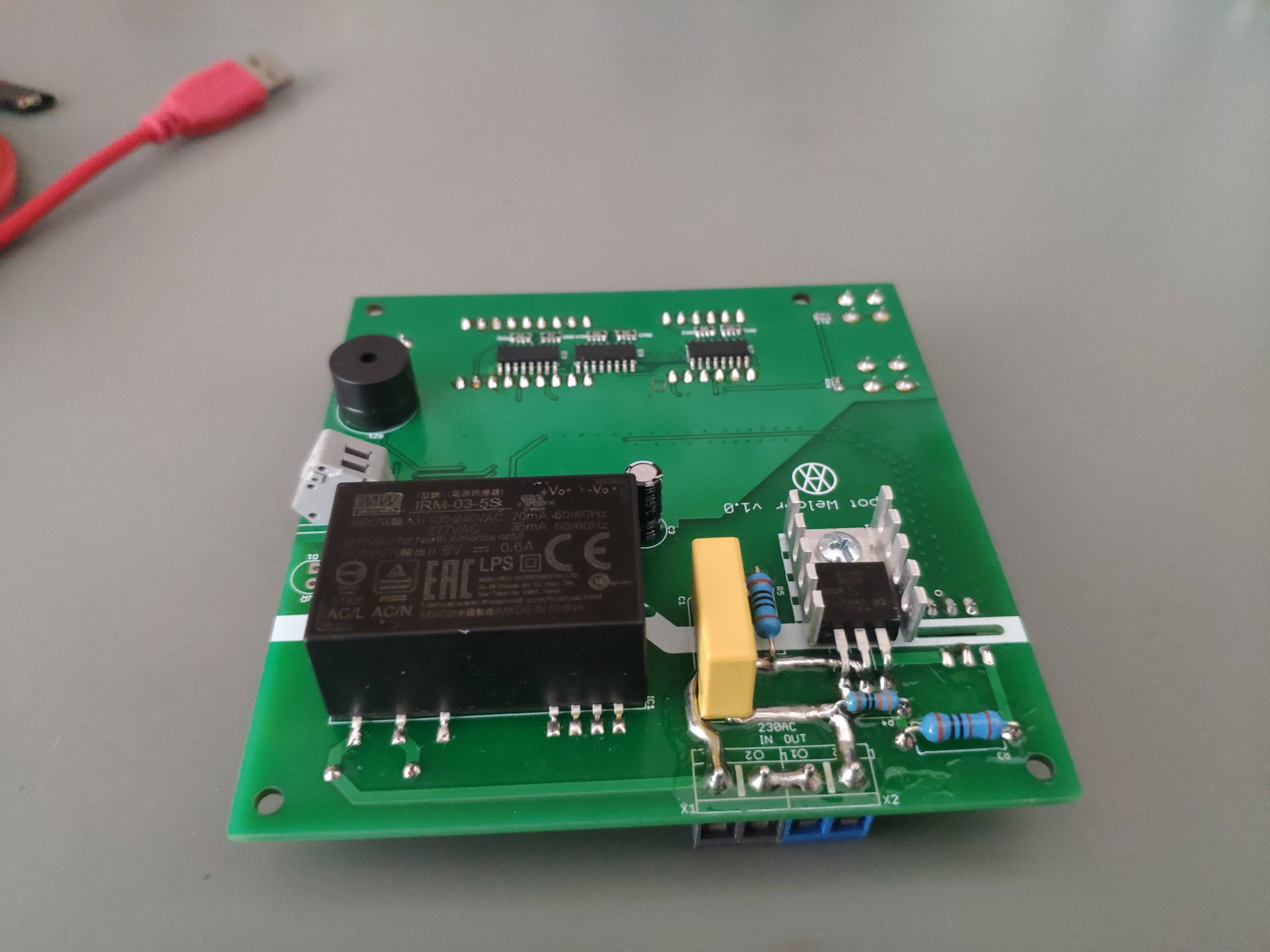
As I said, there is nothing special behind, maybe the SW... . Switching is based on zero-cross witch time calculation. If you chose the pulse mode, times are calculated with 50Hz period respecting. (60Hz needs some SW modifications.) Switch is not starting at zero-cross (as it looks like from first point of view), but at the maximum, 1/50Hz = 20ms -> 5ms or 15ms. Triac has enough power to switch such a load.
The pre-weld feature is used for clean the contacts before "full" weld.

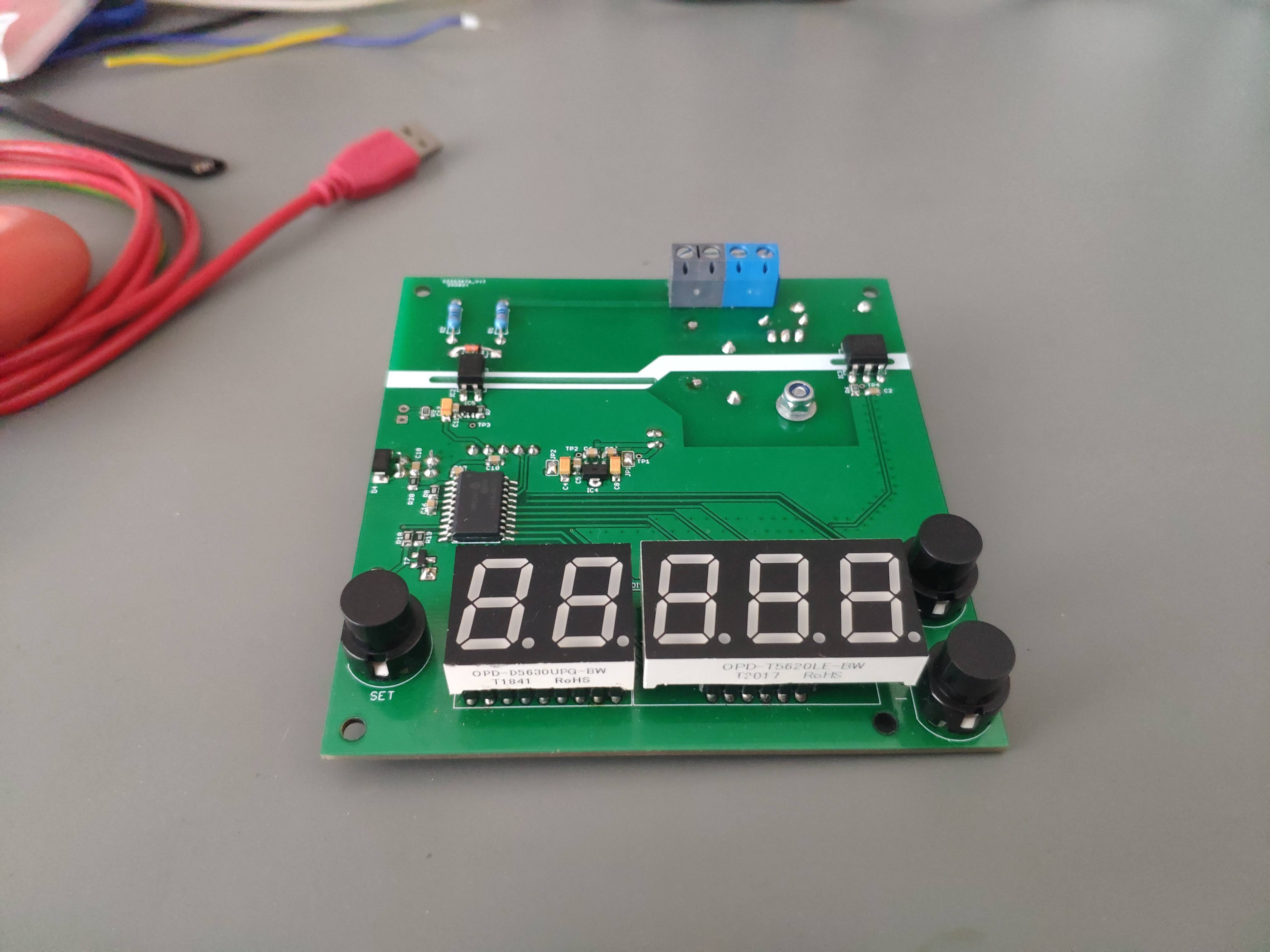
If we look the user interface... there are just two buttons for increase/decrease the value and one for "set" selection. If you want to save the new value into EEPROM, you have to press and hold +/- buttons together. One feature is, that you don't need to wait lot of time to get the higher value. After some seconds without button releasing, the increment/decrements is much faster ;).

There was a little bit of research regarding to handle. The main requirement had to be the floating electrodes. So each of them will get the same contact. Fortunately I founded the right one at the thingiverse. Both are floating and switch is integrated too. So I printed the testing model. After some modifications I was able to use it as it is now.

As a wire I used truth coppered one (not some kind of cheap Chinese variant or something like that). Yes, the price was incredible 50€ for 2m of 1x25mm^2.

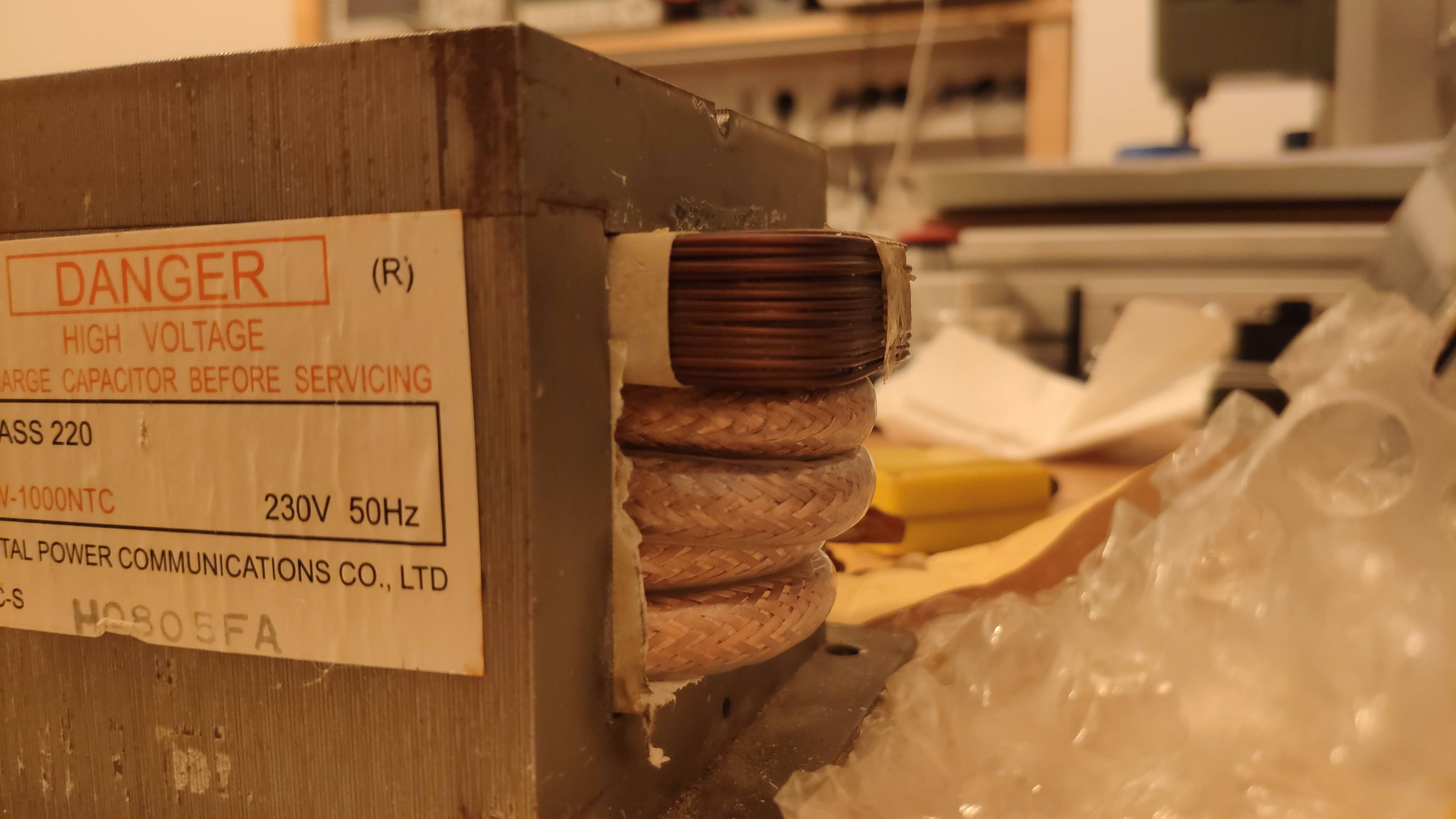
Friend of mine told me, that 4 rounds should be enough. So I had to replace the isolation (It was really a pain), but I was successful.

I designed a custom housing from 2.5mm steel plate. Yes 2.5mm, because the MOT is really heavy. 

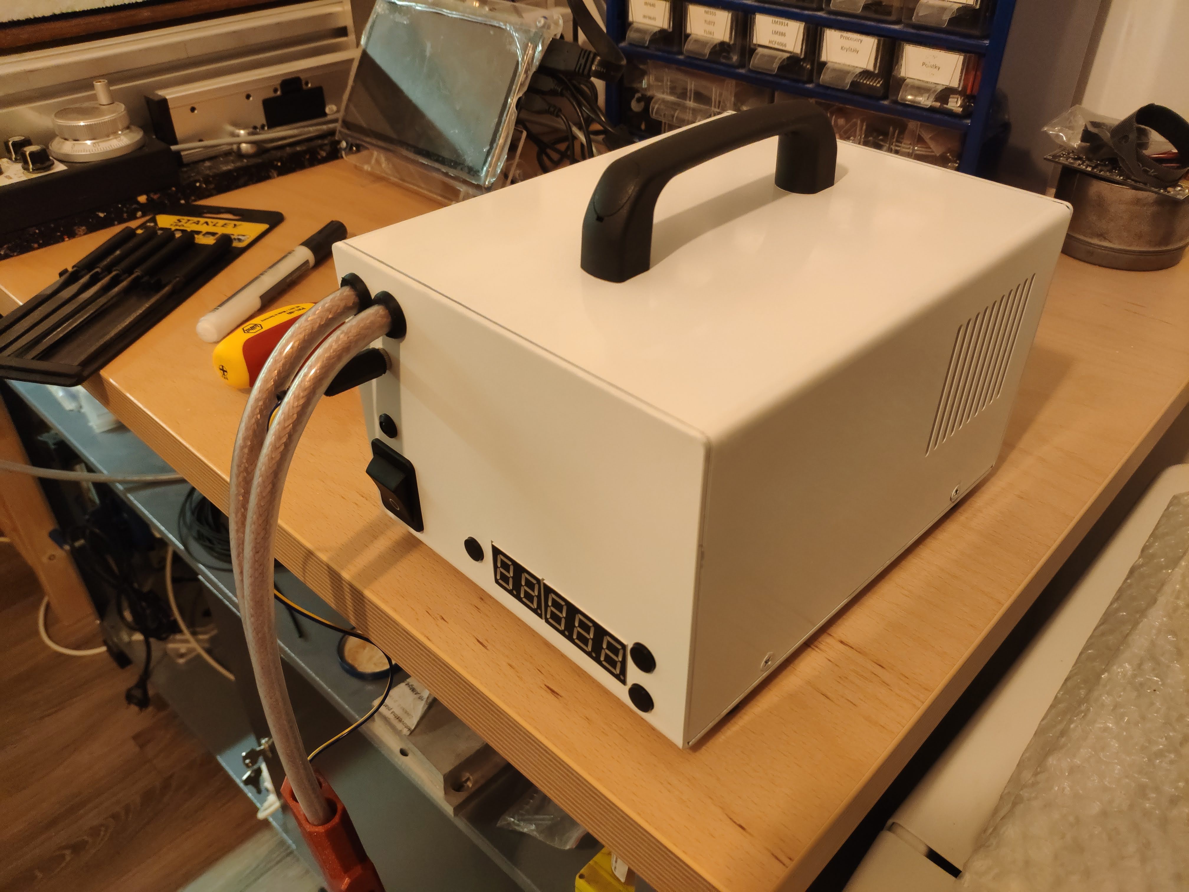
I was also thinking to add some front panel with description, but to be honest. I think is intuitive enough.

Ok, that's it. Maybe a last picture, how the the weld looks like. 

gerber_v1.1.zip

Gerber files

Zip Archive - 329.49 kB - 10/23/2021 at 07:45

Download

BOM_sw.xls

Components

ms-excel - 11.00 kB - 10/23/2021 at 07:46

Download

top_assembly-v1.1.png

TOP layer assembly

Portable Network Graphics (PNG) - 24.88 kB - 10/23/2021 at 17:48

Preview
Download

bot_assembly-v1.1.png

BOTTOM layer assembly

Portable Network Graphics (PNG) - 21.14 kB - 10/23/2021 at 17:48

Preview
Download

FW.zip

MCU Firmware file - v1.0

Zip Archive - 5.13 kB - 10/23/2021 at 07:48

Download

  • 1 × PIC16F18344 MCU, SOIC
  • 1 × IRM-03-5S AC/DC converter
  • 1 × BTA140 Discrete Semiconductors / Thyristors (DIACs, SIDACs, TRIACs, SCRs)Tr

  • DIY

    Andy10/23/2021 at 08:00 0 comments

    When I started to write the description for this project, I wasn't sure, the will be interested for someone. But now I'm really glad to see the results. So I decided to make the project really public, means anyone can build it by own.

    After some more thinking (of course with community pushing :) ) I also made the schematic public. So you can really find more information what's inside, not just the gerbers. To be honest, I'm not going to publish the source-code, but you can flash the firmware as well. Maybe someone just need the schematic like a inspiration can build his own device based on different MCU. So I think, this could be enough.

    So here is the full schematic...

    I published all required files, which are enough for someone who wants to make it by himself (gerbers, assemblies, BOM and FW).

    So that's it... . Many thanks for any kind of feedback.

    One important note, you're working with high voltage, so you should know what you're doing. I'm not responsible for any kind of damage on your health :).


    Happy building!

View project log

Enjoy this project?

Share

Discussions

aji_maxim wrote 03/03/2022 at 16:48 point

Excellent!! Can you post a video showing what the led display shows? Is it dual pulse or single pulse? Can a pneumatic system be added to it?

  Are you sure? yes | no

Andy wrote 03/27/2022 at 11:16 point

Hello,
I can describe it, so the video is not needed I guess.
- First part of display (2 segments)
 - parameter selection
  - cleaning time
  - pause time
  - welding time
  - pulse/continues mode
   - pulses count
   - weld until it's possible

What do you mean by pneumatic system?

  Are you sure? yes | no

aji_maxim wrote 03/31/2022 at 07:18 point

Hi...

Pneumatic system means that a solenoid valve moves the welding tip. If so, it could be used to make a battery pack.

  Are you sure? yes | no

Andy wrote 03/31/2022 at 07:22 point

Ok, so in this case, I'm not going to add anything like that. I guess the current handle system is sufficient enough ;).

  Are you sure? yes | no

Andy wrote 10/23/2021 at 08:05 point

Many thanks for your requests.
I've added all necessary files, which should be enough to make this device by own ;).

  Are you sure? yes | no

Keysers wrote 10/22/2021 at 16:57 point

Hi Andy, sweet and clean project you made! I'm always interested in learning. A schematic would help me tremendously to do that more than gerbers. Keep building!

  Are you sure? yes | no

Brian Christmas wrote 10/22/2021 at 02:02 point

I would also like the schematics and firmware. :) 

Thanks!

  Are you sure? yes | no

perez.ernesto.j wrote 10/22/2021 at 00:18 point

hello

count me in for the source/schematics!!

  Are you sure? yes | no

jaytigra wrote 10/20/2021 at 02:47 point

where is the source code and schematics. is this open source?

  Are you sure? yes | no

Andy wrote 10/20/2021 at 13:18 point

Hi jaytigra!

It's not open for now. I wasn't aware of, that someone else will be interested in this kind of construction :). To be honest, there is nothing special behind. Just LED controlling and MOT switching.

But ok. If someone else requests for it too, I can add the gerbers (maybe schematic) and firmware for MCU.

  Are you sure? yes | no

Similar Projects

Does this project spark your interest?

Become a member to follow this project and never miss any updates