I have uploaded initial photos and instructions but I can enhance these more if there is interest. 3D stl files and OpenScad model is now uploaded for printing and customisation
I will probably create a separate project for the AtTiny85 continuity tests. It is a very simple project but is also a good introduction to the AtTiny85 DigiSpark (and clone) boards.
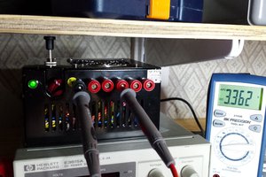
Most of the wiring connections are now shown in included images. I will also add images next for the PSU, switch, fuse and XT60 connector


 zakqwy
 darth_llamah
 Michael Murillo
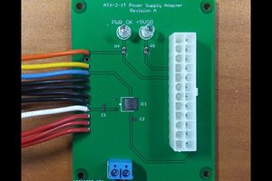
 Dave's Dev Lab
This is awesome. I have actually been planning a project similar to this but based around a soldering station. I am still working on the layout of the individual components before I start designing the controller board.
Since a soldering station has a pretty strong PSU and a hot air station needs plenty of air, most lab devices/tools can be powered off those, bringing the costs way down. For example my current soldering station has a 800W power supply which would be plenty to run a 30v 10A power supply while the iron is off. There is no reason to have both when you can't use both at once.
So far I am planning on:
Devices
-Reflow oven
-Board heater
-Air filter
-Power supply + usb charger
-multimeter
-transistor tester /lcr meter
-temp sensor
-7" display
-light / light ring
-Parts drawer, tip cleaner, etc.
Hand Tools
-Solder iron
-Hot air
-solder sucker
-soldering tweezers
-paste dispensing
-vacuum pick/place
-digital microscope
-3rd hand
I am open to adding other things that would use the same components such as an esp32, stm32, Atmega or maybe an additional ADC or other IC as long as it is not too expensive.