 mircemk
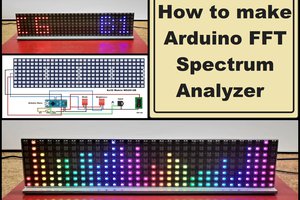
This time I will show you how to make a visually beautiful spectrum analyzer that can also function as an Audio VU Meter and Waterfall Analyzer. The device is made on 16x16 LED matrix with WS2812 chip on diodes which costs about 12 USD.
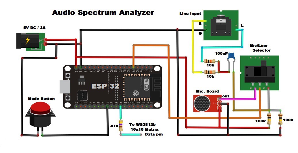
When we use Line input, the incoming stereo signal is first converted to mono using two 10K resistors, then through a 100nF capacitor to block DC. The signal is then biased by two 100k resistors to 3.3V / 2 = 1.65V to be read by the ADC. Using the Microfon board is much simpler than the line-in method, but you will be limited to the frequencies that you can detect by the sensitivity of the microphone. The matrix is controlled from a single button. There are five modes of operation, three of which are Spectral Analyzers, one Audio VU meter, and one Waterfall Analyzer.
The button functions are:
- Single press: Change pattern
- Long press: Change brightness
- 3 button presses in 2 seconds: Set to auto-change pattern
- 5 button presses in 2 seconds: Turn off display
The original code is written by Scott Marley on GitHub, which as the author says is heavily modified from the example originally written by G6EJD. I made the project on a ready-made 16x16 matrix which simplifies the way of making and I also made very small adjustments to the code for this case, and you can download it below.
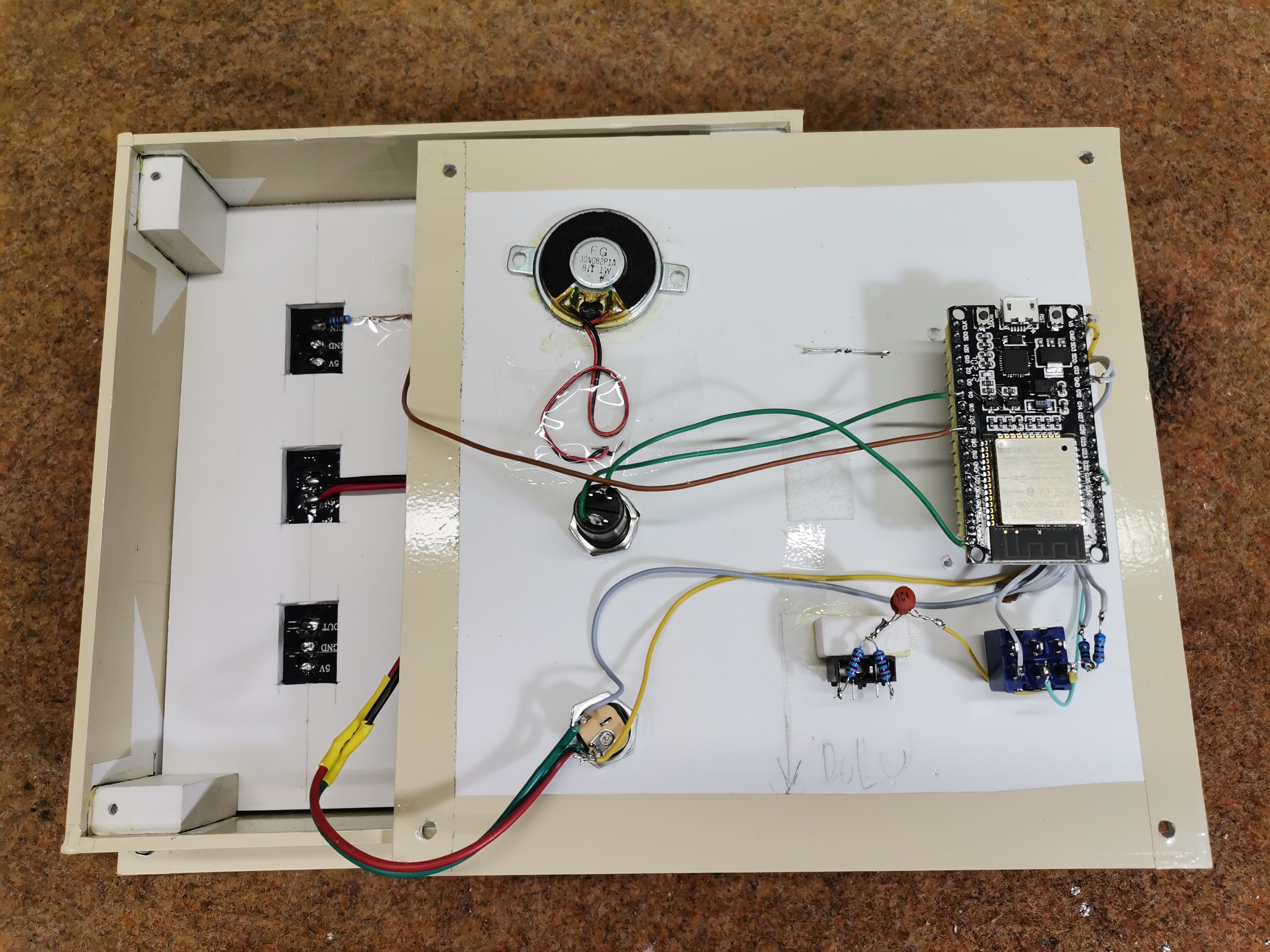
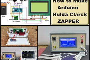
The device is simple to make and contains several components:
- ESP32 Microcontroller
- 16x16 WS2812 Led Matrix
- Small microphone board which contains a preamplifier chip
- five resistor
- one capacitor
- and One button
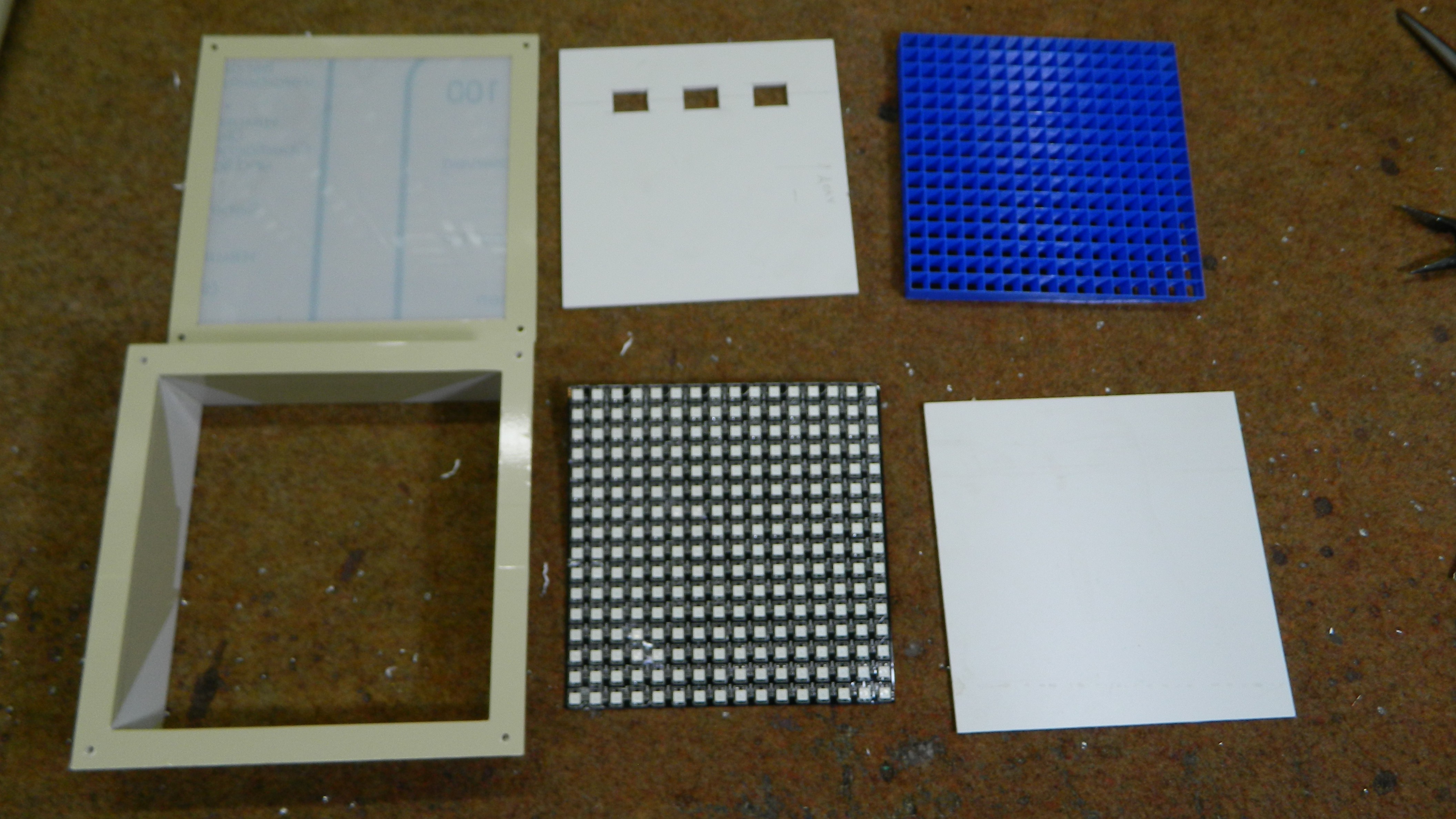
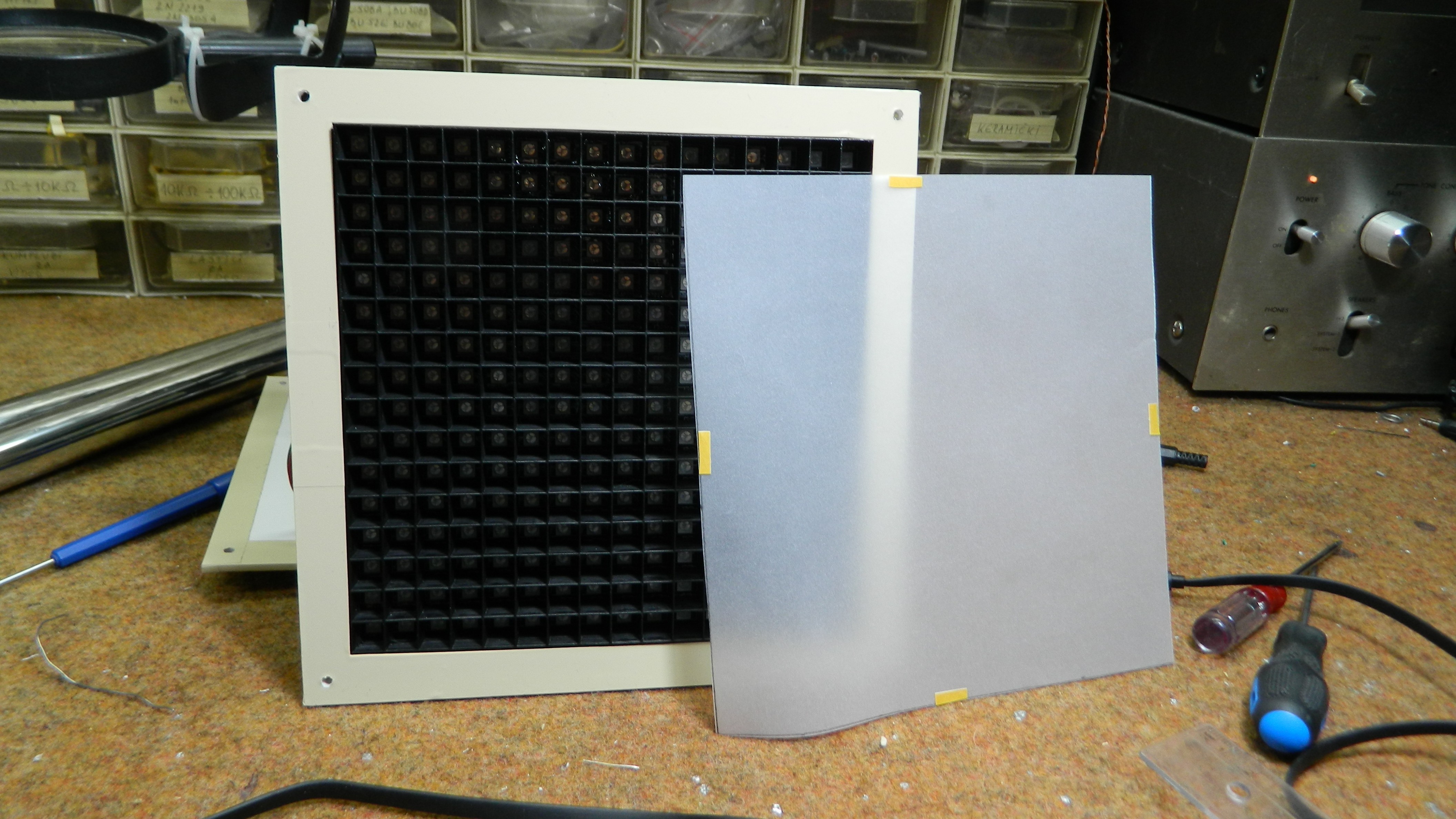
If you want the device to look identical to this, then you also need a 3D Printer. To get a better visual effect, the matrix diodes should be separated by partitions. For this purpose, a grid is printed on a 3D printer. I created a custom grid that requires less material and printing time. You can download the STL files at the link below. A tracing paper should be placed over the grid to diffuse the light.
During the device description, the device was operating in microphone mode. To run Analyzer via the line input, we need to plug in an audio signal. We can change the sensitivity in the code, depending on the strength of the source signal. By single button press, we change the patterns. The long press serves to change the brightness. There are three levels of brightness. With 3 button presses in 2 seconds, we Set the device to auto-change pattern. And with 5 button presses in 2 seconds wi will Turn off display.
An interesting case is when we input a sinusoidal signal with a certain frequency. For that purpose I use Tone Generator. As can be seen, this is a spectrum analyzer instrument for frequency domain analysis. In this way the device can be used as a simple tool for frequency analysis in the lab, primarily intended for learning.
Finally, the device is built into a suitable box made of PVC board and coated with a self-adhesive color label.


I love the pixellated look -- the suggestion of a dark border around each cell is great.