mircemk
This time I will show you how to make a power supply unit that will cost you less than $ 10 if you have an old power supply from a laptop or something similar.
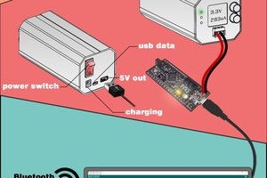
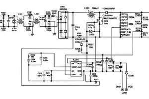
The heart of this device is this small module ZK-4KX Buck-Boost Convertor that you can get in one of the online stores for a very low price. Specifically, I bought it for a total of $ 8.6 on eBay.
This amazing little module has almost all the features that expensive commercial power supplies have. I think the most important feature is a constant current setting that will surely save you a lot of electronic components and devices. Another advantage is that instead of standard potentiometers, a Rotary encoder is used which is physically much more durable, and also the required value is changed in steps, and can be adjusted very precisely. This is a Buck-boost DC-DC converter which means that at the input we can bring any voltage in the range from 5V to 30V, and at the output we get voltages from 0.5V to 30V. In this particular example, I put 12V at the input, and at the output we get voltages in the range from 0.5V to 30V. We need to keep in mind that the total power that can be charged to the output is slightly lower (about 20 percent) than the total power to the input power supply. As I was writing this review, I noticed that a very similar project to this is presented on Hackster, so I decided to show you some features that are not described there.
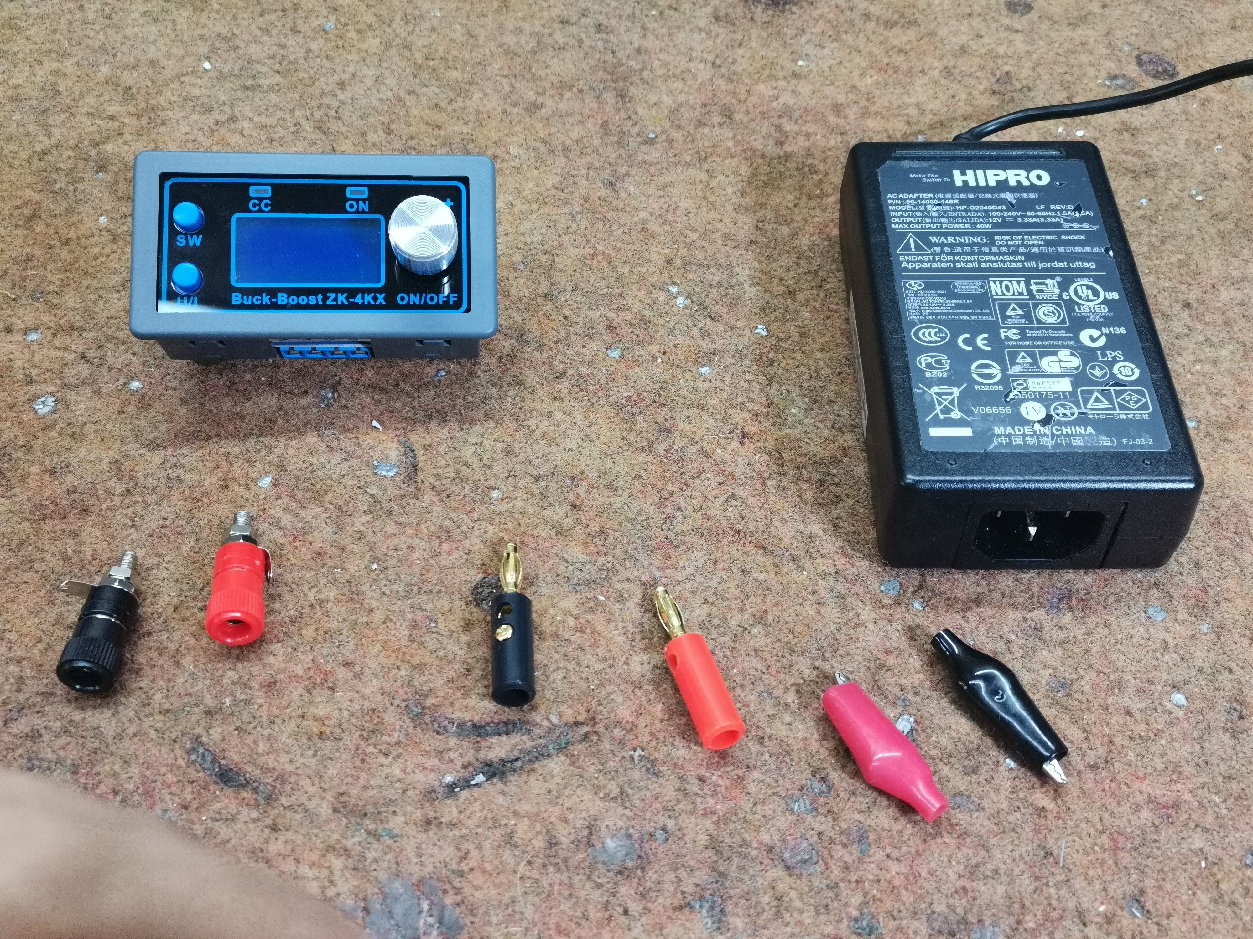
All we need to make the device are these few parts:
- The power supply I use it has an output of 12 Volts 3.3 Amps or a maximum output power of 40 Watts. This means that at the output of the power supply we will be able to connect a consumer with a maximum power of about 34 watts. Of course, at the input we can use a more powerful source, for example 90Watt power from a laptop and then at the output we will get twice as much power. However, the maximum power, with additional cooling should not exceed 120 watts. The connection is very simple and all we have to do is connect the power supply to the V-in and the terminals to V-out.
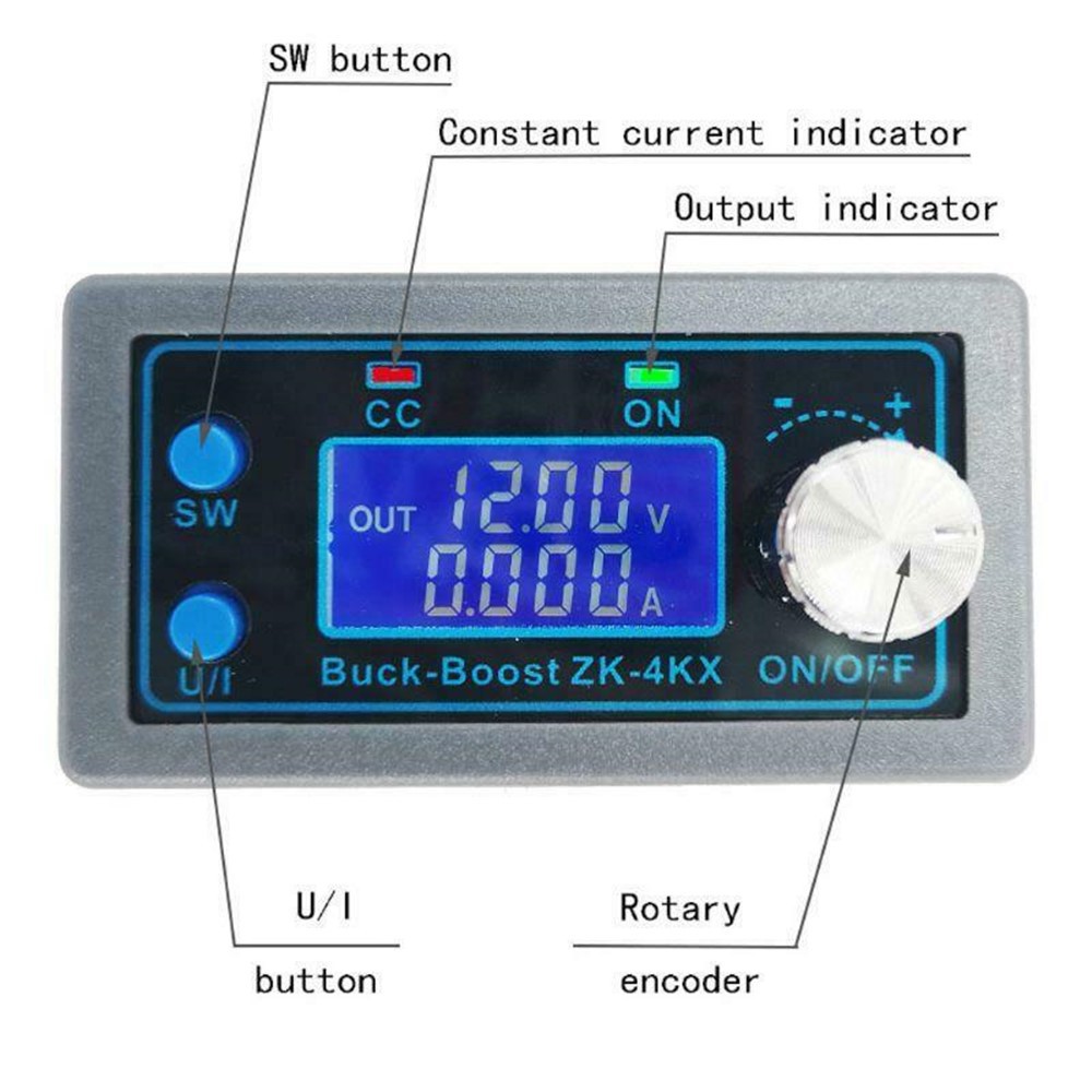
For a start, the most important thing is to learn how to set the voltage to the correct value, and how to turn it on and set the CC mode. With one push of the U / I button we enter the voltage setting and then with the button from the encoder we select a change step. By turning left and right we change the value of the voltage. With the next press of the U / I button we enter the constant current mode and now in the same way with the rotary encoder, we can set the maximum allowed current at the output.
And now let's do a short experiment:
Let's take a high-brightness white LED with a maximum allowable voltage of 3.2 volts, with a current of up to 20 milliamperes flowing through it. Connect it to 12V on the power supply in normal mode. As we can see, the diode will light up strongly for a few milliseconds and then burn out because a very large current will flow through it. Connect it to 12V on the power supply in normal mode. As we can see, the diode will light up strongly for a few milliseconds and then burn out because a very large current will flow through it. Connect it to 12V on the power supply in normal mode. As we can see, the diode will light up strongly for a few milliseconds and then burn out because a very large current will flow through it. Connect it to 12V on the power supply in normal mode. As we can see, the diode will light up strongly for a few milliseconds and then burn out because a very large current will flow through it. In this way we can protect very expensive and sensitive electronic components, especially bearing in mind that with this device we will often power the Homemade and untested devices.
For example, for the first time we test a 100-watt Homemade Audio Amplifier that has a rated current of several Amps, and a so-called Quiet Current of...

 hesam.moshiri
 engineerkid1