 finallyfunctional
This project is for my support rig I created for my passive VR shoes. You can see it in action here.
Features
- Full 360 continuous turning
- Crouching (distance is adjustable)
- Sitting (distance is adjustable)
- Easy to turn while walking
- Relatively quiet when walking
- No welding required to build it
- Low weight
- Can be stored up along the ceiling
Not sure if you should build this rig or my free standing one? You can read my comparison of the two here.
Here is the BOM, with the total price for parts ranging from $208 to $290 as of the time of this writing (Apirl 4, 2022).
Scroll down or go here for build instructions.
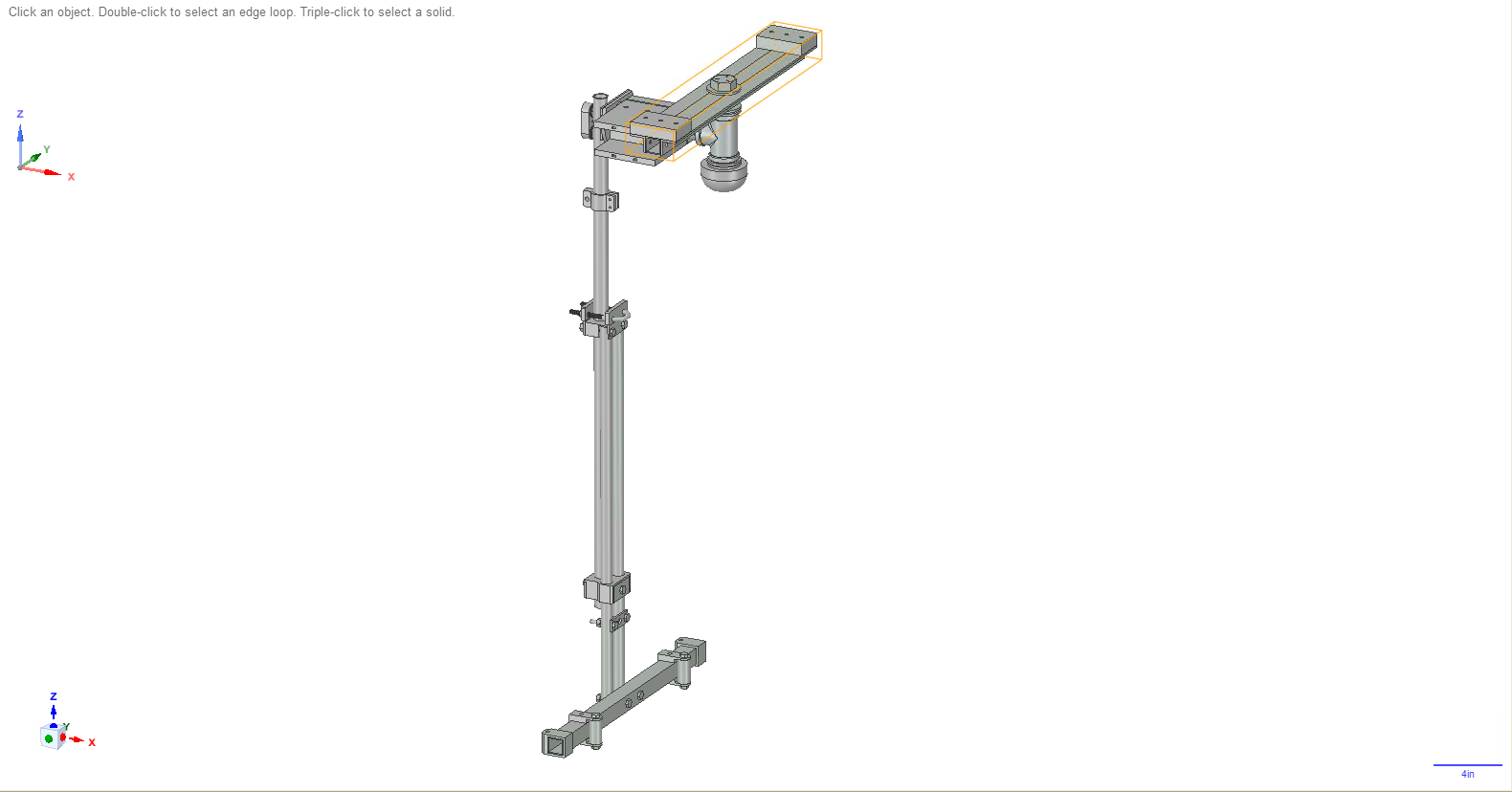
To view the 3D model file you can go here. It opens up in Designspark Mechanical. This project is open-source so feel free to take the file and do whatever you want with it.
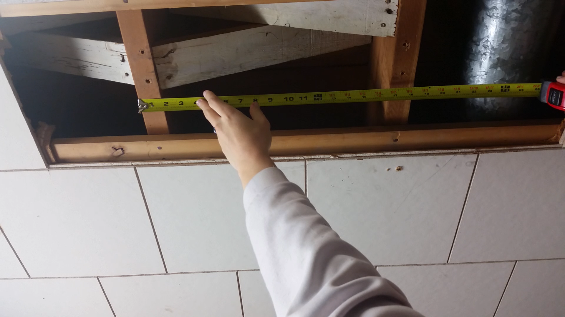
 Take your 1in angle (row 2 in BOM) and cut 2 pieces, each piece should be as long as the distance between the outer edges of each beam. In my case, I cut 2 18in long pieces.
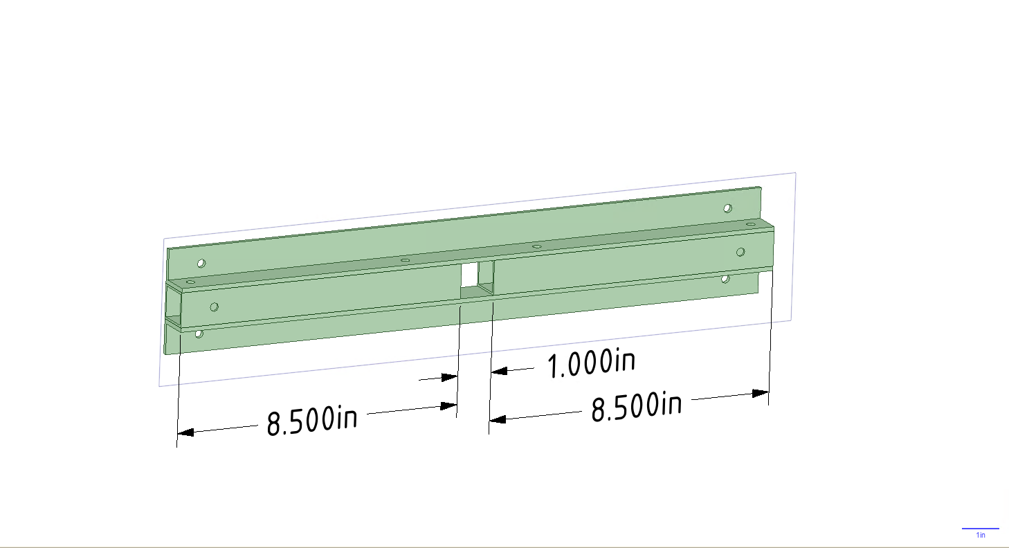
 Kaspar Emanuel
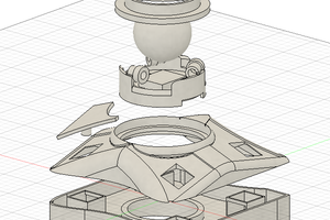
 skylerthuss
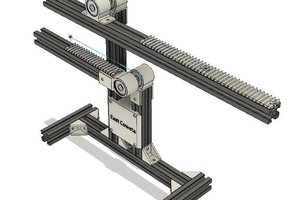
 Jason Cho
 Ken Yap