0%
0%
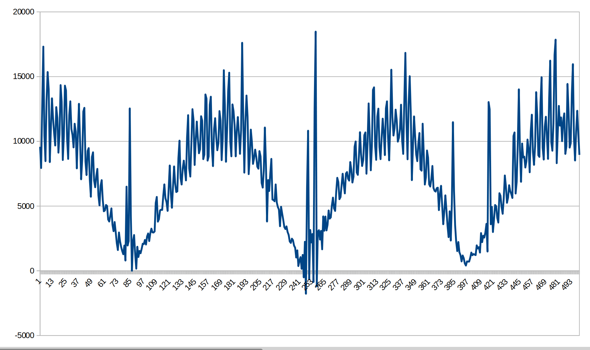
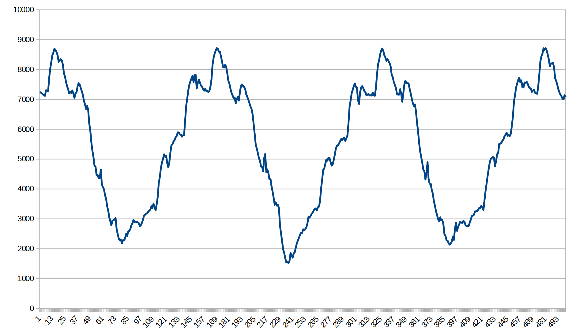
Brushed motor speed control with stable RPM
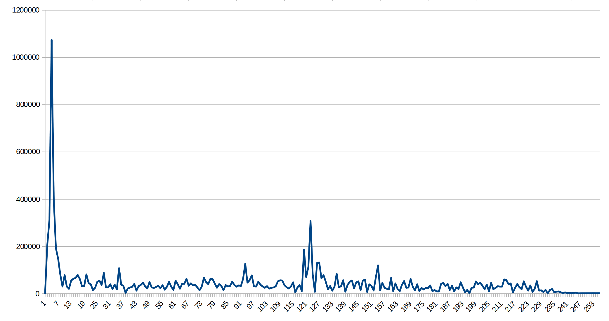
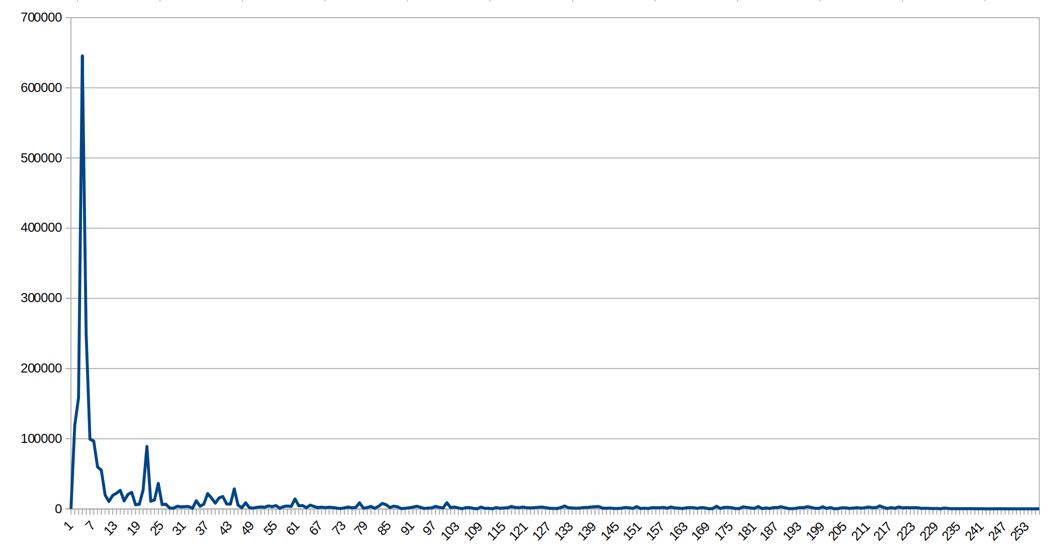
Uses brush current pulses to measure speed
 Vitaly
Become a Hackaday.io member
Already have an account? Log in.
Just one more thing
To make the experience fit your profile, pick a username and tell us what interests you.
Pick an awesome username
hackaday.io/
Your profile's URL: hackaday.io/username. Max 25 alphanumeric characters.
Pick a few interests
Projects that share your interests
People that share your interests

 Mrinnovative
 Simone Tolomei
 ridonkulus
Found this by link from https://forum.allaboutcircuits.com/threads/universal-motor-speed-control-using-commutator-frequency-as-feedback.195800/
No connection - just saying someone found this.