 Keith
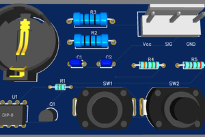
KeithThis board was developed with a servo motor the size and power of a car starter motor. The power amplifier was the size of a huge book, and had a big power resistor to dump braking energy.
2021-11-08
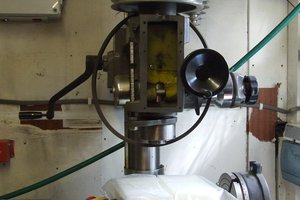
Someone had dumped a treadmill by the bins (instead of taking it to the recycling centre) so I dismantled it to take the steel to the scrap metal dealer. As a bonus, I salvaged the massive 2 horsepower (1500 W) 180V permanent magnet motor. Which sounds exactly like a servo motor to me!
Now I need a windfall high-power amplifier and a feedback encoder...


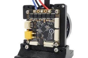
 Josh Pieper
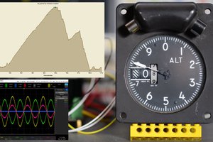
 Sci
Sci