Close
0%
0%

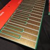
BADGE FOR SUPERCON.6 / November 2022

After three years... Supercon again!
And the new badge too!

Similar projects worth following
YouTube video: https://youtu.be/ix__enrtYF4

4-bit processor simulated by 16-bit MCU. Registers, flags, ALU, SP, two Data Memory pages, current Program Word and some internal logic states are displayed in binary form, with 272 LEDs.
- A total of 31 instructions
- Processing speed: adjustable (in runtime) from 250,000 ips to 0.5 ips, plus Single Step
- Program Memory: 4096 pgm words × 12 bits
- Data Memory: 256 nibbles (32 visible in real time)
- 5-deep Subroutine Stack
- Opcodes/Operands are 4-bit aligned, visible on 3×16 LED disassembler display
- Three ways of programming:
1. Direct, using on-board buttons in Binary or Select mode
2. Indirect, using 2-pass assembler, created by Mike Szczys
3. Save/Load to/from computer or other badge (using serial I/O) or internal flash
- Bootloader for firmware update
- I/O port with 4-bit IN and 4-bit OUT
- 3V (2×AA) Battery supply
- SAO port with Serial I/O
- Detailed User Manual
- Dimensions 17.5×9.

Reflash to version Badge Berlin 2023.zip

Please download, unzip and read the attached .TXT file

x-zip-compressed - 10.75 kB - 04/28/2023 at 19:31

Download

Badge Berlin 2023.zip

- The new version of firmware, created in February 2023. - The year and v1r1 extension are generic, that`s why it's 2022 v1r1. - Contains new functions described in Manual Rev4a.pdf, and some minor bug fixes - This version of firmware was prepared for the Berlin conference, but due to a manufacturing error in China, the old version was programmed. - To open the project, install MPLAB X IDE - To program using MPLAB X IPE, use this file: \dist\default\production\Badge2022_v1r1.production.hex (the year and v1r1 extension are generic)

x-zip-compressed - 322.08 kB - 04/27/2023 at 18:14

Download

1 Manual Rev4a.pdf

User Interface, Commands and Modes of Operation

Adobe Portable Document Format - 1013.21 kB - 11/11/2022 at 20:45

Preview
Download

2 Instruction Set Rev4.pdf

Detailed explanation of all instructions

Adobe Portable Document Format - 1.05 MB - 11/03/2022 at 02:25

Preview
Download

3 SFR Rev4a.pdf

Special Function Registers. NOTE: Revision 4a (Nov.03.2022) contains an error fix (page 24, KeyReg). Please use this revision if you have Rev4 or lower.

Adobe Portable Document Format - 647.36 kB - 11/04/2022 at 03:07

Preview
Download

View all 10 files

Enjoy this project?

Share

Discussions

Ray Erdinc wrote 02/11/2024 at 14:59 point

Hi,  Just got my Supercon 6 Badge, fantastic bit of kit, love it!  Having a play with the on-ine stuff but get this error with the on-line assembler, any advise please, Windows 10/11 and Edge:

"Warning: fopen(./tmp/example_65c8dfddd6ffd): Failed to open stream: Permission denied in /var/www/html/badgeasm/output.php on line 27Fatal error: Uncaught TypeError: fwrite(): Argument #1 ($stream) must be of type resource, bool given in /var/www/html/badgeasm/output.php:28 Stack trace: #0 /var/www/html/badgeasm/output.php(28): fwrite() #1 {main} thrown in /var/www/html/badgeasm/output.php on line 28"

Also this when trying the links for instruction set, manual and the other links:

This XML file does not appear to have any style information associated with it. The document tree is shown below.

"<Error>
<Code>AccessDenied</Code>
<Message>Access Denied</Message>
<RequestId>H06JNVV269H12TR6</RequestId>
<HostId>pH6STfWKAmWyhhMFXA9tQ1hfcqdxz1amSmZtnXVCEcuGuB4NvGKrBWvNfoBIuG0sTexaXT6DS0cLrpzqyFbouwkU5KW7iY3p</HostId>

</Error>"

  Are you sure? yes | no

AlexBuilds wrote 10/31/2023 at 11:03 point

Hey there, i have a question regarding ADC from Instruction Set Rev4a. Is it correct, that the C flag is reset if (RY) < (RX) and set if not ? Shouldn´t it be set if Overflow occurs and reset otherwise? As stated on ADD opcode? I also found some outdated pieces of documentation on page 2 in the Instruction Set Rev4a: it is stated, that "ALU" mode supports instructions with triangular sign. Should it be in "DIR" mode?

  Are you sure? yes | no

Voja Antonic wrote 10/31/2023 at 14:28 point

You are right, it's an error in the manual. It should be similar like in ADD instruction, only "if (RX)+(RY)>15" should be replaced by "if (RX)+(RY)+(C)>15". Thanks!

In outdated manuals ALU means DIR. It's just a matter of terminology.

  Are you sure? yes | no

Ale o co chodzi wrote 06/05/2023 at 12:20 point

are You planing internelizoation project? for example Polish language?

  Are you sure? yes | no

Бойко Неов wrote 05/07/2023 at 15:03 point

If I build the badge myself, I must upload the firmware with Pockit and it will not have a bootloader, is that correct?

  Are you sure? yes | no

Voja Antonic wrote 10/31/2023 at 14:32 point

Sorry for the late reply, I didn't get a notification for your post. If you use the PICKIT to flash a new MCU, you will have the bootloader too, as it's a part of the HEX file.

  Are you sure? yes | no

Michael Möller wrote 05/02/2023 at 15:17 point

I just "bricked" my badge trying the firmware update - I think. Nothing lights up anywhichway. Suggestions?

  Are you sure? yes | no

Voja Antonic wrote 05/02/2023 at 15:26 point

Reflash it again, in the same procedure. You can't affect the bootloader area, so it's safe.

The last (and safest) method should be programming using PICKIT.

  Are you sure? yes | no

Michael Möller wrote 05/03/2023 at 07:40 point

Happiness is a badge with flashing lights :-)

  Are you sure? yes | no

[deleted]

[this comment has been deleted]

Voja Antonic wrote 05/02/2023 at 15:14 point

Seems more like the RXRD pointer was not updated correctly after reading from RX buffer. I tried to locate the problem in the source text (without simulating it on the badge), but I couldn't do it quickly. I couldn't even see how writing to TX buffer could affect RX FIFO contents. Sorry, I have to do it later, as I'm in another project at the moment. I'll check it later and reply here.

  Are you sure? yes | no

Michael Möller wrote 05/03/2023 at 07:46 point

Thanks for looking into it. I deleted my query when the badge went dead, but you'd obviously already read it. What I wrote was along the lines:

It seems that if there is data in the FIFO buffer, and I write to Serial output port, then the next read seems to read what was just sent. If the FIFO buffer is empty, I write, and then data is received all is OK.

I can send you the rather simple code loop, otherwise it is on the Hackaday Discord channel under Badge-hacking

  Are you sure? yes | no

Michael Möller wrote 05/10/2023 at 14:53 point

I have been experimenting and there are two flaws:

1: You must not send serial if there are characters in the input buffer - it gets confused and reads the last sent character instead of the incomming.

2: WrFlag.0 set to 1 does not work for send character. Nothing comes out.

I can send a little testcode suite and extended info direct to you.

  Are you sure? yes | no

Paul wrote 04/14/2023 at 20:28 point

@Voja Antonic I received a board from a Berlin Hackaday participant.  I haven't updated the FW, so I'm guessing it's whatever was shipped.  I found two issues, not sure where I should post them so I'm trying here.  

I can't get the Alt+Dep+ (insert instruction) working.  I've got some code I've written and I need to insert some instructions.  When I use Alt+Dep+, nothing happens.  Am I doing something wrong?

When I run a program it resets the LED brightness value.  I guess this might be expected if it's clearing all the special function registers, but for me it's easier to see the help text when it's not so bright.  Would there be a way to remember the LED brightness?

  Are you sure? yes | no

Voja Antonic wrote 04/14/2023 at 20:42 point

I'm not sure about the LED dimmer, but the problem with ALT+DEP could be due to the wrong firmware version. I'm currently in Europe, but I'll be back on Wednesday, so I'll check it and update the firmware as soon as I'm back. Sorry about this!

  Are you sure? yes | no

Paul wrote 04/14/2023 at 20:47 point

Great.  Spent the first week figuring out, so now I'm trying to create slightly more difficult projects.  Lots of fun!

  Are you sure? yes | no

Paul wrote 04/27/2023 at 13:54 point

Have you had a chance to look at this?  Is the source open?  @Voja Antonic 

  Are you sure? yes | no

Voja Antonic wrote 04/27/2023 at 19:23 point

Try it now. This version was ready for the Berlin conference, but, due to a manufacturing error in China, the old version (November 2022, used on Pasadena Supercon) was programmed.

  Are you sure? yes | no

Paul wrote 04/28/2023 at 18:40 point

@Voja Antonic do you mean update to the FW in the Badge Berlin 2023 zip?  ANd that's the badge22.o file in Badge2022_v1r1/build/default/production?

  Are you sure? yes | no

Voja Antonic wrote 04/28/2023 at 19:35 point

No, please use the .BIN file
Download and unzip "Badge Berlin 2023.zip"

  Are you sure? yes | no

Paul wrote 04/28/2023 at 20:46 point

@Voja Antonic I looked for *.BIN from https://cdn.hackaday.io/files/1825687810989312/Badge%20Berlin%202023.zip and I didn't find anything.  It has a root dir Badge2022_v1r1. Am I missing the .BIN?

  Are you sure? yes | no

Voja Antonic wrote 04/28/2023 at 20:50 point

When you unzip it, you get two files: Badge Berlin 2023.bin and Reflash.txt

  Are you sure? yes | no

Voja Antonic wrote 04/28/2023 at 20:52 point

I think that you downloaded the wrong file. You need "Reflash to version Badge Berlin 2023.zip"

  Are you sure? yes | no

Paul wrote 04/28/2023 at 21:22 point

Great, I see it now.  Thanks!

  Are you sure? yes | no

Paul wrote 04/30/2023 at 15:13 point

@Voja Antonic the FW update fixed my insert problem, thanks!  However, the LED brightness still resets each time I run a program.  Slightly annoying because in some lighting they are too bright and I can read the text next to them on the board.  Minor problem I suppose, but perhaps an easy fix.

  Are you sure? yes | no

alan_r_cam wrote 11/30/2022 at 23:59 point

I'd like to see an emulator for this, running on Android tablet.

  Are you sure? yes | no

Tachion wrote 11/29/2022 at 13:17 point

When Polish language version?

  Are you sure? yes | no

Paul wrote 11/26/2022 at 19:59 point

If I did try to build it myself, what skills do I need?  I've ordered pcbs before and can solder.  Any really small SMD parts?  How much time does it take to put together?

What I love about this is project is that it is so accessible.  When my son asks me, "how does a computer work?" I believe this can be an answer.  It appears to expose an important layer of computing that is otherwise hard to grasp.  And it fits in your hand and lays out everything in front of you.  Such a great idea!

  Are you sure? yes | no

Voja Antonic wrote 11/26/2022 at 20:26 point

If you want to get the first soldering skills, I would strongly recommend practicing on some other platform, as this is an advanced challenge. Note that there are two decoders with only 0.635 mm pitch, which is not easy to solder.

First, you need a soldering iron with a good, thin tip, and I can say that 90% of soldering irons I've seen in workshops are unusable for such a task. Then you need a thin solder and a soldering flux, which you will wash with alcohol later.

Start with LEDs first (watch polarity!), then ICs (watch polarity again!), passive components and then wash it firmly in alcohol, with a small brush. Then solder buttons, they don't like washing in alcohol, as some oily flux can cover contact surfaces. But you can clean surrounding area by a piece of cloth with a little alcohol. At last, solder the Through-hole components, connector and battery holders.

Don't hurry! I need a few hours to solder one badge, which has 364 components. Here's how i do it - which does not mean that you have to do it the same way. First, I put a little solder on only ONE side of every component place on the PCB (all other have to be flat). For convenience, it is the right or top side (I'm right-handed). The I use a fine tweezers to place the component with my left hand, and use my right hand to hold the soldering iron and fix the component on one side only. Sometimes it is enough to use the solder which I already put on the pad in the first phase, and sometimes I need to take a little more. When I'm finished with one type of components (for instance LEDs), then I check the position of every component, as this is the last chance to fix the precise positions. Then I rotate the PCB for 180° and solder another side, holding a thin solder wire in my left hand. The I turn it again, and repair all pads from the first phase, sometime with some more solder.

With ICs, you will need a good loupe (I use the watchmaker's one), so that you can see shorts and bad joints on the fine ICs. Use a lot of flux here!

The most important thing: don't rush! Good luck!

  Are you sure? yes | no

Ken Yap wrote 11/26/2022 at 22:50 point

With the BOM and CPL files for PCBA you could get most of it assembled. This design has a lot of repeated parts and values and is amenable to PCBA. Sourcing particular parts like the MCU and getting them to the assembler is another problem but it's one you have to tackle anyway. Or you could do those bits yourself; I've found soldering SMD ICs far easier than SMD passives.

Sorry, not offering to take any steps in this direction. I like the design though.

  Are you sure? yes | no

Paul wrote 11/26/2022 at 23:00 point

Thanks @Ken Yap , any general idea of the cost.  I know a PCBs is pretty cheap.  Under $25 I think.  What is the general increase in cost with PCBA?

  Are you sure? yes | no

Ken Yap wrote 11/26/2022 at 23:10 point

@Paul  Sorry, it's highly dependent on design, board size, components, availability, offers, assembly house, etc. You just have to collect quotes. Here's an investigation for a small design of mine: https://hackaday.io/page/11900-costing-assembly-service-for-my-pcb

  Are you sure? yes | no

Paul wrote 11/28/2022 at 19:22 point

@Ken Yap I'm getting a quote from JLCPCB but the CPL file for this project isn't identical.  They want Designator, Mid X, Mid Y, Layer, Rotation.  I guess I could just convert and drop the extraneous information?  Suppose that won't change the results?

[edit]  Converting to an XLS and fixing the columns (some weren't offset properly), and it at least identifies the parts.  It doesn't find many of them, like a lot of the resistors, so not sure the format in the ZIP is compatible with JLCPCB, but they do have a chat which might help.

Also, the preview shows all the buttons off the board.  Hilarious, as I imagine a robot dropping pieces on the floor :)  Not so funny as I'm paying for it :(  Anyways if you have any sage advice, I'd appreciate it, but I can update here as I make progress, or not.

  Are you sure? yes | no

Ken Yap wrote 11/28/2022 at 22:58 point

@Paul There is no standardisation of BOM and CPL formats. You must follow the requirements of the fabrication house. JLC publishes their requirements on their website. CSV is easier to work with than XLS as a format, you can edit with a text editor. It's a pity the original design files weren't published. For my investigation I used KiCad so I had full control over the fabrication output files.

  Are you sure? yes | no

Paul wrote 11/29/2022 at 02:59 point

Thanks Ken, guess I was thinking if it has a name, there should be a it's a standard but I guess PCB and pick and place is still pretty immature.  But this is really good info.  I also found out that this particular site doesn't like the spaces in the parts, so that's why I wasn't seeing the LED parts.  And I found out the misalignment or the parts on their 3d render is OK, and can be fixed later.

The last thing to figure out is why only some of the resistors parts aren't found while others are.   I think I might just need to rename some of the columns in the BOM or CPL.

FYI, I think the quote I've computed so far is around 120.00 USD.  Assuming that is accurate, it is a reasonable price for me.  

Perhaps the biggest blocker now is the main AT-MEGA.   Seems to be difficult to find.  I do see bulk amounts available, but not sure how to unlock just 1 of those. 

  Are you sure? yes | no

Ken Yap wrote 11/29/2022 at 03:22 point

@Paul Remember you have to order minimum 10 if you want all of them assembled. There are minimum requirements for parts + margin for wastage, so you may have to order 10 or 20 MCUs even if you only need 1. Or you could buy that yourself and solder it yourself. You could also try to interest others in a group purchase. Also I didn't look but does the design have parts on both sides? You'll have to pick one side for PCBA, and do the other side yourself.

  Are you sure? yes | no

Paul wrote 11/29/2022 at 14:14 point

More great advice @Ken Yap !  Appreciate all your help so far.  I will check into that next.  Currently I've chosen the 2 side assembly.  1 side has like 300 LEDs/buttons, and the other side ~20 SMD parts.  I'm I bit reluctant to do myself.  I've soldered a few SMD parts, and that was pretty tedious.  Seems like an entire weekend project, which is already packed with other hacking :)  At this point I'm thinking I can do the microcontroller, since it seems to be the hardest part to have placed, but only because you said it's easier :)  But perhaps manual is going to be the only option.


Anyway, I'll continue to post progress in case it helps somebody else.  Maybe more fodder for a future article :)

  Are you sure? yes | no

Paul wrote 11/29/2022 at 14:28 point

Got a quote for one PIC24FJ256GA704-I/PT from Heisener... $66 USD :( 

  Are you sure? yes | no

Paul wrote 11/24/2022 at 18:52 point

I want one as well.  I have researched a bit and I think one idea is that a Group Buy is the best way to get a final product rather than building one.  But I'm not sure if anybody has created a Group Buy nor do I know much about it...yet.

  Are you sure? yes | no

hwang_hoyoen wrote 11/23/2022 at 19:43 point

Sorry I am new in here. I have a question. How can i purchase this one?

  Are you sure? yes | no

Paul wrote 11/24/2022 at 18:53 point

Meant to post a reply ^^^

  Are you sure? yes | no

Voja Antonic wrote 11/25/2022 at 20:46 point

Sorry, it's not for sale. It's for conference visitors.

However, it is an open source project, so you can build it. The complete documentation can be downloaded. Just scroll up and click "View all 9 files".

  Are you sure? yes | no

hwang_hoyoen wrote 11/25/2022 at 20:48 point

okay, Thanks you so much

  Are you sure? yes | no

Malcolm wrote 11/21/2022 at 22:15 point

Hello! I've been looking at having one of these badges made using all the design files. I have a question though.

Due to the chip shortage I haven't been able to find the brains of the whole thing, PIC24FJ256GA704-I/PT anywhere. I did however spot some lesser PIC24FJ128GA204 MCUs online and was wondering if I could retro fit one into the design. The pin count, package, and pin out of the J128GA204 all match the original MCU, but I'm wondering if there are some other incompatibilities I might be overlooking. (Assuming that having half the flash space would be okay since I thought the firmware hex file is less than 128Kb.)

  Are you sure? yes | no

Voja Antonic wrote 11/22/2022 at 09:04 point

I don't think that it will work with the existing firmware. If you download the "1 Manual Rev4a.pdf" and look at the last page, you will see the memory organization of the system PIC. Firmware takes only about 48K of the program memory, but the rest is used as the firmware backup during the bootload process and for Flash storage, for program saving. 

So if you run it on the 128K MCU, it will stop execution and perform the Address Error Trap, which is fatal for program execution. The problem will occur in the initialization routine, shortly after Reset, when it loads pre-programmed samples to the Flash Program memory.

  Are you sure? yes | no

Malcolm wrote 11/22/2022 at 23:32 point

Darn! I just got the fabbed PCBs too. Well, thank you for the detailed response. When considering the flash space, I wasn't even thinking about these other mechanisms that go into simulating the 4-bit processor. Unless anyone knows of any possible way to get one of these chips, I'll have to hope the lead time doesn't keep getting pushed out. I guess I can use this time to learn more about the software portion and hopefully alleviate any future headaches too. 😅

  Are you sure? yes | no

Adrian Freed wrote 11/21/2022 at 21:35 point

Here is the project page with the documentation on the DAC/ADC board I gave you for the badge: https://hackaday.io/project/188326-badgeio-dacadcsiggenbuffers-for-supercon6

  Are you sure? yes | no

Voja Antonic wrote 11/21/2022 at 21:42 point

It's a good documentation. Thanks, Adrian!

  Are you sure? yes | no

Adrian Freed wrote 11/12/2022 at 04:14 point

Thanks for this great badge, Voja.
A few days before the conference an important inventor died at the age of 100: : Kathleen Booth. She designed and built some of the first computers and assemblers.  I wrote this assembler/code synthesizer for your badge in her honor: https://github.com/adrianfreed/Supercon6BadgeWork

  Are you sure? yes | no

Adrian Freed wrote 11/12/2022 at 04:39 point

Incidentally you can read about old machine design thoughts of the 40's and the first assembly code notations here: https://albert.ias.edu/handle/20.500.12111/7942

  Are you sure? yes | no

Ben Combee wrote 11/11/2022 at 06:57 point

I just spotted a typo in rev4 of the Manual. In your list of synthetic instructions on page 36, for LSL RY, I think that should be "ADD R0, 0", not "AND R0, 0".  The AND won't clear the carry, but the ADD will without affecting R0's value.

  Are you sure? yes | no

Voja Antonic wrote 11/11/2022 at 18:16 point

Both "ADD R0, 0" and "AND R0, N" reset Carry, but the first one affects Z and V flags too. If you look at the tables on the back of the badge, or pages 25-27 of the Instruction Set book, you will see that OR R0,N sets, AND R0,N resets and XOR R0,N toggles Carry. This is a way to affect Carry without affecting any register.

The similar approach was used in Z80, but OR/AND/XOR instructions only reset C, and two independent instructions (SCF and CCF) are used to set/complement Carry.

However, your note helped me to see my error in the Manual, as AND R0,0 actually clears R0. If you want to keep the contents of R0, then it's better to use AND R0, 0xF. This will be corrected in the next revision of the manual.

  Are you sure? yes | no

Ben Combee wrote 11/11/2022 at 19:35 point

Ah, I think my confusion was that the text for AND R0,n does indicate the C is unconditionally reset, while AND RX,RY says that C isn't affected. Thanks!

  Are you sure? yes | no

Mohit Bhoite | मोहित भोईटे wrote 11/08/2022 at 19:30 point

@Voja Antonic 
I can't imagine the amount of work you must have put into creating the user manuals and other documentation for this badge. They are all beautiful! I heard that you are using Corel Draw for creating these documentations, is that right? If so, what does that process look like? Are all the symbols created manually or is there a clipart library that you use for the schematics. How do you add junction symbols on the wires? manually?
Thanks!

  Are you sure? yes | no

Bob Long wrote 11/06/2022 at 23:37 point

For anyone making their own and wondering about LED orientation, I think it's anode (+) on the left and/or down for all of them. The pick-and-place file does not use cathode-left for zero-rotation. I had to check by importing the PCB into KiCAD, and then double checked by looking for a die in the high-res photos.

@Voja Antonic, could you please correct me if I am wrong? Would be good to get orientation information into the Placement.zip images

  Are you sure? yes | no

Voja Antonic wrote 11/07/2022 at 15:47 point

You are right about LED orientation, anode is always left, down or left-down. There's a marking which is invisible once it's not needed anymore, on the top silkscreen layer under the rightmost button. Enlarge the last (6th) image in the project gallery and note the yellow symbols at the bottom right. There's a number of LEDs (272) and orientation.

  Are you sure? yes | no

Bob Long wrote 11/07/2022 at 15:54 point

Ah, that's a great silkscreen indicator! I missed that. Thank you!

  Are you sure? yes | no

James Newton wrote 11/06/2022 at 17:18 point

@Voja Antonic May I humbly suggest that you edit the description to link the text 
"assembler, created by Mike Szczys"
In the description to the repo at:
https://github.com/Hack-a-Day/2022-Supercon6-Badge-Tools

  Are you sure? yes | no

TomKeddie wrote 11/05/2022 at 03:41 point

@Voja Antonic the files for my East Van addon board are at https://github.com/TomKeddie/prj-supercon2022/raw/12320199498d3a410aec8e213062e2ced3b3eca3/badge/Supercon%202022%20East%20Van%20Badge%20Addon%20Schematic.pdf and https://github.com/TomKeddie/prj-supercon2022/raw/main/badge/Supercon%202022%20East%20Van%20Badge%20Addon.pdf

Thanks for all your hard work.

  Are you sure? yes | no

Similar Projects

Does this project spark your interest?

Become a member to follow this project and never miss any updates