 Subhajit
In this IoT project, I have shown how to make an IoT-based Home Automation project using ESP32 and the new Blynk IoT app to control an 8-channel relay module from the manual switch & smartphone.

During the article, I have shown all the steps to make this Blynk home automation system.
Tutorial Video on new Blynk ESP32 Smart Home
This Blynk ESP32 control smart relay has the following features:
- Control home appliances with WiFi (Blynk IoT app).
- Control home appliances with Blynk web dashboard.
- Control home appliances with manual switches or push buttons.
- Monitor real-time feedback in the Blynk IoT App.
- Control appliances without WiFi from manual switches.
So, you can easily make this home automation project at home just by using an ESP32 and relay module. Or you can also use a custom-designed PCB for this project.
Required Components:

- ESP32 DEVKIT V1 board
- 8-channel SPDT 5V Relay Module
- Push Buttons or Switches
You can make this project just by using ESP32 and 8-channel relay module. But if you use PCB then you need the following components.
Required Components for the PCB:

- ESP32 DEVKIT V1
- Relays 5v (SPDT) (8 no)
- BC547 Transistors (8 no)
- PC817 Optocuplors (8 no)
- 510-ohm 0.25-watt Resistor (8 no) (R1 - R8)
- 1k 0.25-watt Resistors (10 no) (R9 - R18)
- 10k 0.25-watt Resistors (1 no)
- LED 5-mm (10 no)
- 1N4007 Diodes (8 no) (D1 - D8)
- Push Buttons (9 no) or Switches
- Terminal Connectors
- Jumper
- 5V DC supply
Required Software:
1. Blynk IoT app (Blynk 2.0)
2. Arduino IDE
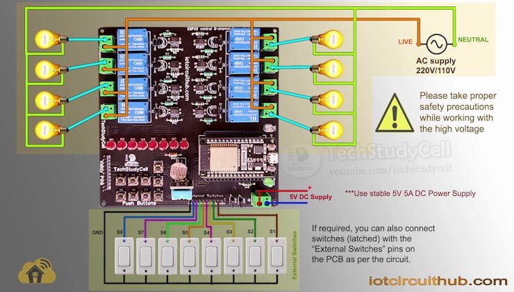
Circuit Diagram of the ESP32 Home Automation Project:
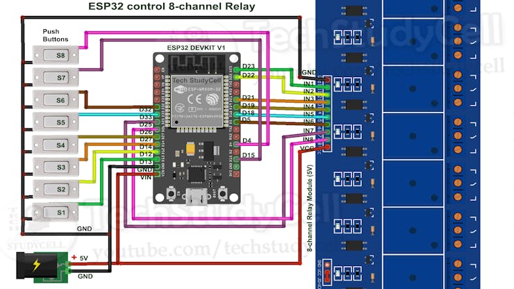
This is the complete circuit diagram for this home automation project. I have explained the circuit in the tutorial video.
The circuit is very simple, I have used the GPIO pins D23, D22, D21, D19, D18, D5, D25 & D26 to control the 8 relays.
And the GPIO pins D13, D12, D14, D27, D33, D32, D15 & D4 are connected with Switches to control the 8 relays manually.
The Wi-Fi indicator is connected with the D2(GPIO-2) pin, connected with the blue LED mounted on the ESP32 board.
I have used the INPUT_PULLUP function in Arduino IDE instead of using the pull-up resistors.
I have used a 5V 5A DC power supply.
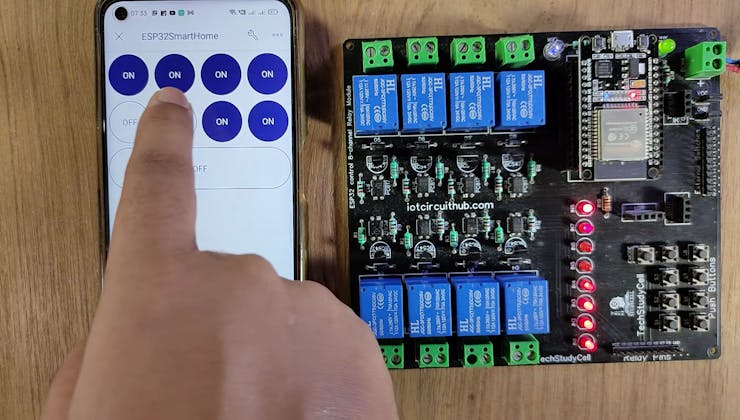
Control Relays With Blynk IoT App:

If the ESP32 is connected with WiFi, then you can control the home appliances from Blynk IoT App.
You also use multiple smartphones to control the appliances with Blynk IoT App. For that, you have to log in same Blynk account from all the smartphones.
In this way, all smartphones will be sink to the Blynk server. You can control, monitor the real-time status of the relays from anywhere in the world with the Blynk App.
Control Relays Manually With Buttons or Switches:
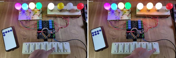
You can also control the relays from the switches or pushbuttons.
If the ESP32 is connected with Wi-Fi, you can monitor the real-time feedback in the Blynk IoT App.
And if the Wi-Fi is not connected, still you can control the relays from manual switches.
Please refer to the circuit diagram to connect the switches.
Designing the PCB for ESP32 IoT Projects:

To make the circuit compact and give a professional look, I have designed the PCB after testing all the features of the smart relay module on the breadboard.
You can download the PCB Gerber file of this home automation project from the following link:
Order the PCB from JLCPCB:
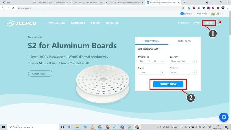
After downloading the Garber file you can easily order the PCB
1. Visit https://jlcpcb.com and Sign in / Sign up
2. Click on the QUOTE NOW button.

3. Click on the "Add gerber file" button. Then browse and select the Gerber file you have downloaded.
Uploading the Gerber File and Set the Parameters:
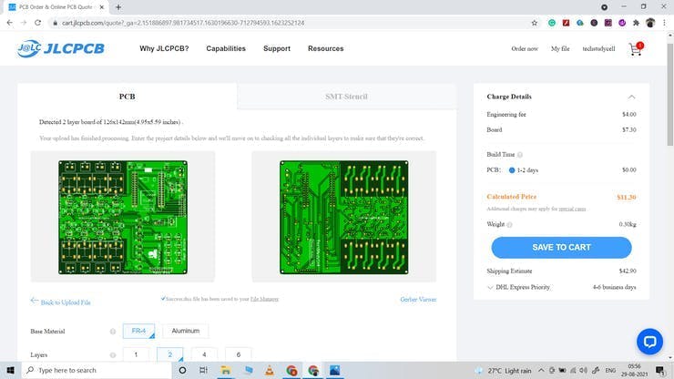
4. Set the required parameter like Quantity, PCB masking color, etc.

5. After selecting all the Parameters for PCB click on SAVE TO CART button.
Select Shipping Address and Payment Mode:

6. Type the Shipping Address.
7. Select the Shipping Method suitable for you.
8. Submit the order and proceed with the payment.
You can also track your order from the JLCPCB.com
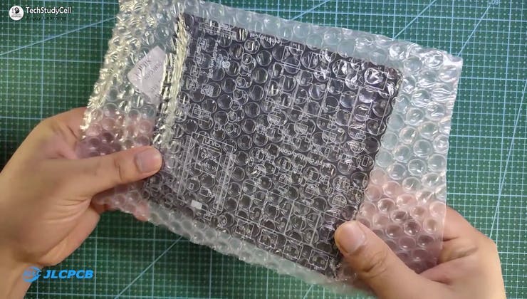
My PCBs took 2 days to get manufactured and arrived within a week using the DHL delivery option.
PCBs were well packed and the quality was really good at this affordable price.
Solder All the Components on PCB:
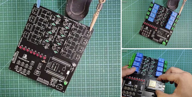
After that, I have soldered all the components as per the circuit diagram.
Then connect the ESP32 board, DHT11 sensor, LDR, and 1838 IRreceiver with PCB.
Create FREE Blynk Cloud Account:

For this smart house project, I have used the Blynk IoT Cloud Free plan.
Click on the following link to create a Blynk Cloud account.
https://blynk.cloud/dashboard/register
- Enter email ID, then click on "Sign Up". You will receive a verification email.
- Click on Create Password in the email, Then set the password, click on Next.
- Enter your first name, click on Done.

After that Blynk cloud dashboard will open.
Create a New Template in Blynk Cloud:
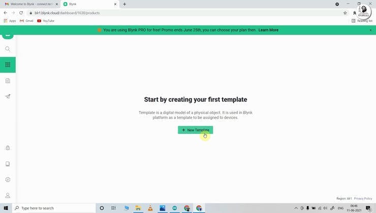
First, you have to create a template in the Blynk cloud.
- Click on New Template.
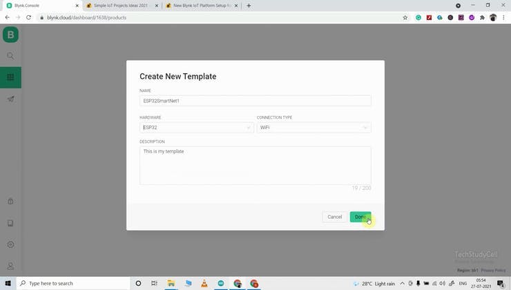
- Enter a template name, select the hardware as ESP32, and the connection type will WiFi.
- Then click on DONE.

You will get the BLYNK_TEMPLATE_ID and BLYNK_DEVICE_NAME after creating the temple.
The BLYNK_TEMPLATE_ID and BLYNK_DEVICE_NAME will be required while programming the ESP32.
Create a Datastream in Blynk Cloud:

After that, you have to create Datastreams. Here I will control 8 relays, so I have to create 8 Datastreams for relays and 2 Datastreams for sensors.
- Go to the Datastreams tab.
- Click on New Datastream and select Virtual Pin.

- Enter a name, select the virtual pin V1, and the datatype will be Integer.
- Then click on Create.
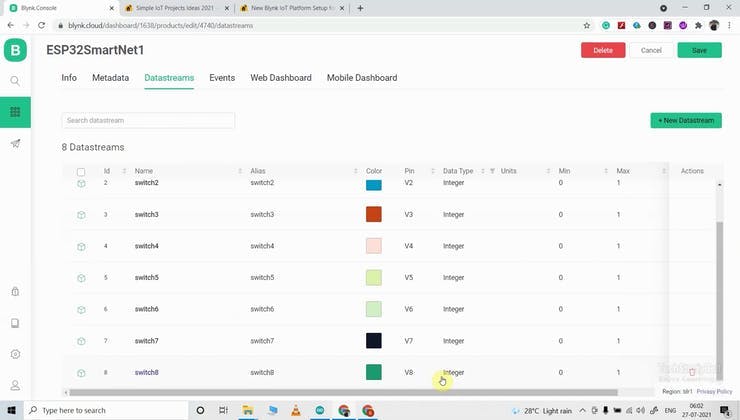
In a similar way, create 8 datastreams with virtual pin V1 to V8.
Then create 1 datastream to turn off all the relays using V9.
Set Up Blynk Cloud Web Dashboard:

Now go to the web dashboard tab.
Drag and drop 8 Switch widgets
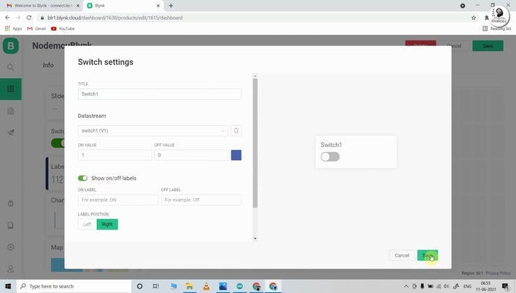
Go to the settings of each widget, and select a Datastream.
Please refer to the tutorial video for more details.
Program the ESP32 for This Blynk Project
First, download the source code for this project.
Download and install the following libraries in Arduino IDE
- Blynk 1.0.1 Library: https://github.com/blynkkk/blynk-library
You have to keep all the 9 files in the same folder.

- Open the.ino file in Arduino IDE.
- In the code, you have to update the BLYNK_TEMPLATE_ID and BLYNK_DEVICE_NAME.
- After that, select the DOIT ESP32 DEVKIT V1 board and proper PORT.
- Then upload the code to ESP32 Board.
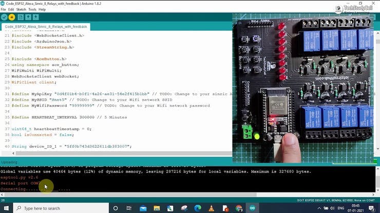
While uploading the code to ESP32, if you see the "Connecting....___" text, then press the BOOT button of the ESP32
Update the WiFi Credentials Through OTA:

After programming the ESP32, you have to update the WiFi credentials from the Blynk IoT app.
In the tutorial video, I have explained all the steps to update the WiFi credentials to ESP32 through OTA.
Configure Blynk IoT Mobile Dashboard:
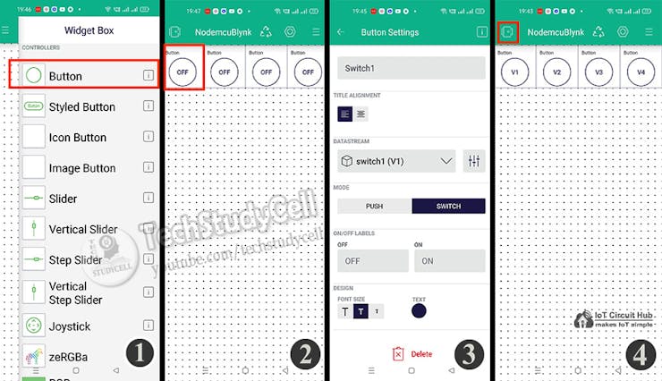
- Select the template that you have already made.
- Go to the Widget box (on the right) to add widgets. Add 8 Button widgets from Widget Box.
- Go to Button widget settings.
- Enter the name, select Datastream, Mode will be Switch. Then exit.
- After configuring all the Buttons tap on exit.
Testing the PCB:
After the ESP32 connects with the Blynk server, the WiFi indicator LED blinks very slowly.
Before connecting the appliances, please check whether you can control the relay from the Blynk IoT app.
Connect the Home Appliances With Relay:
Connect the 8 appliances and external switches with the PCB as per the circuit diagram.
Please take proper safety precautions while working with high voltage.
Connect 5-volt DC supply with the PCB. (I have used my old mobile charger 5V 5Amp)
Turn on the 110V/230V supply and 5V DC supply.
Finally!! the Blynk Home Automation System is Ready:
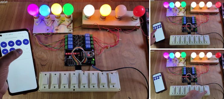
Now you can control your home appliances in a smart way.
I hope you have liked this new Blynk home automation project. I have shared all the required information for this project.
I will really appreciate it if you share your valuable feedbacks. Also if you have any query please write in the comment section.
Thank you & Happy Learning.