 Louis H
Why did I make it ?
1500 bucks elliptical trainer was unusable due to electronics failure. UI welcome screen was looping forever and it was not possible to set any training program or even a simple motion resistance. The trainer price is explained by high mechanical quality, but it is useless without electronic. After two failed reparation attempts, and prohibitive cost for replacement boards from resellers, we found preferable to made a new electronic board using cheap electronic modules.
How to drive the trainer resistance ?
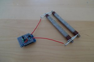
As you can see on the picture below, the resistance is obtained using an electromagnet which field acts on a flywheel. After some research on internet, we found that electromagnet could be driven by a constant current source or by PWM. These second option would be less expensive but could cause issues due to the high inductive load.

Making the circuit
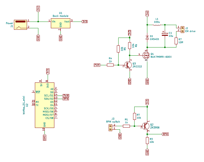
Having a look at the original board, we quickly recognize a PWM drive topology with a power MOSFET, a flywheel diode, LC filtering and fuse Resistor. So we were confident that inductive load will be well driven using this same topology.

Now we know the components needed to pwm drive the electromagnet. The rest of the board is much more classic: a PNP based interface for RPM switch and a ESP8266 module to bring all this to live. Here is the principle schematic we ended with:
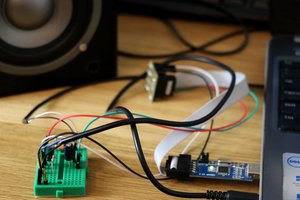
Let's put all this on a breadboard and we are ready to program and test the circuit !
First test
First test objective is to feel trainer resistance versus PWM frequency and duty cycle.
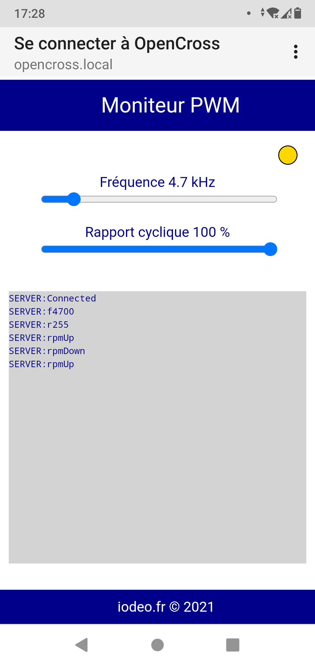
As I had only limited access to the trainer, I made a software that enable change PWM settings using a webapp called PwmMonitor hosted by the ESP8266 in AP mode. This way I didn't need to bring a computer for programing. This was also proof of concept for the final UI as we will discuss later.
PwmMonitor uses websockets to send the commands and also displays received data in a textarea for debug concerns. Code is available on project repository. Picture below shows how it looks.
Here are the observations:
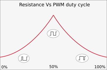
- Trainer resistance is obtained at any PWM frequency, but it is not sensitive to PWM duty cycle at frequencies above 10kHz.
- Resistance can be changed using PWM duty cycle for PWM frequencies below 1kHz. This is the case down to 100Hz, which is ESP8266 lower limit.
- For these low frequencies, resistance increased for duty cycle from 0 to 50% and decrease from 50% to 100%.
- Electromagnet makes audible sound with PWM frequency lower than 20kHz.
Well, at this point we know we can control the trainer, that is a good start !
However, the trainer makes audible sound which we tried to mitigate with a second test by lowering the PWM frequency below the ESP8266 limit of 100Hz.
Second test
The objective of this test was to try a PWM frequency below the human audible 20Hz limit. Since ESP8266 PWM supports is from 100Hz to 40kHz, we used timer to "manually" drive the output using ticker library which is already provided in ESP8266 Arduino core. Note that using delay() is not allowed since it would stop ESP8266 from handling WiFi connection.
The pwm works with 2 tickers. The first one sets periodically output HIGH and redefines once the second ticker to set output LOW after given duration. The period is 90ms and we can set durations from 0 to 45ms with 5ms steps. This gives 9 level of pwm from 0% to 50% duty cycle at 11 Hz frequency. Code is available in final OpenCross program (finally disabled from compiling with #ifndef FREQ).
Observations at 11Hz:
- PWM driver is working and is sensitive to duty cycle
- Maximum trainer resistance seems less strong that at 100Hz frequency
- A little noise is still audible but it is jerky this time
Conclusion was a bit disappointing: we lose in driver efficiency and we still have noise !
After all, 100Hz noise is similar to 50-60Hz humming sound from main AC we are all used to. So this is not that boring.

 biemster
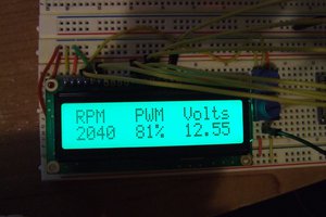
 Łukasz Podkalicki
 Daphne
Been looking at doing something similar to this with my elliptical but wanted to make it work as a remote "game controller" for "walking simulator games". This way I can watch the large monitor in front of my elliptical and have it change speeds in the game in response to the speed I'm walking. Additionally, I was thinking of using a repurposed Wii nun-chuck joystick on one of the handles to allow turning left and right. All this so I have an interactive walking experience to alleviate boredom. The 8266 would work well using either WiFi or Bluetooth to the game running on a NUC PC (I have several of these). The pièce de résistance would be to change the resistance in relation to going up or down hills but without access to the game programming that would be nearly impossible. On the other hand, using my phone, I could take a page from your book and change it via a simple app. Very cool!