 Rudraksha Vegad
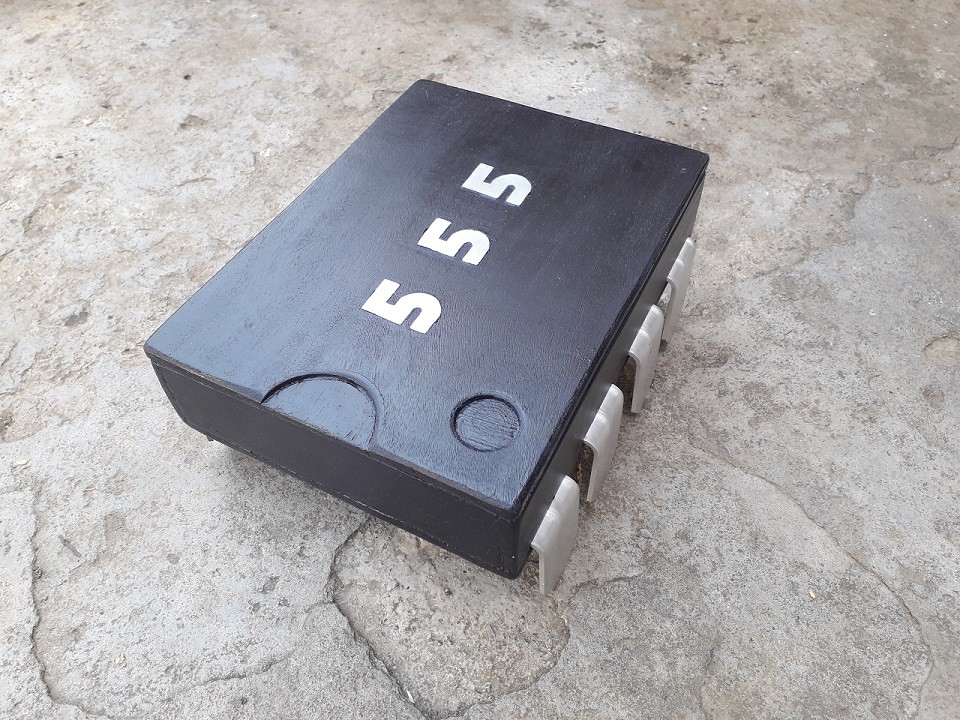
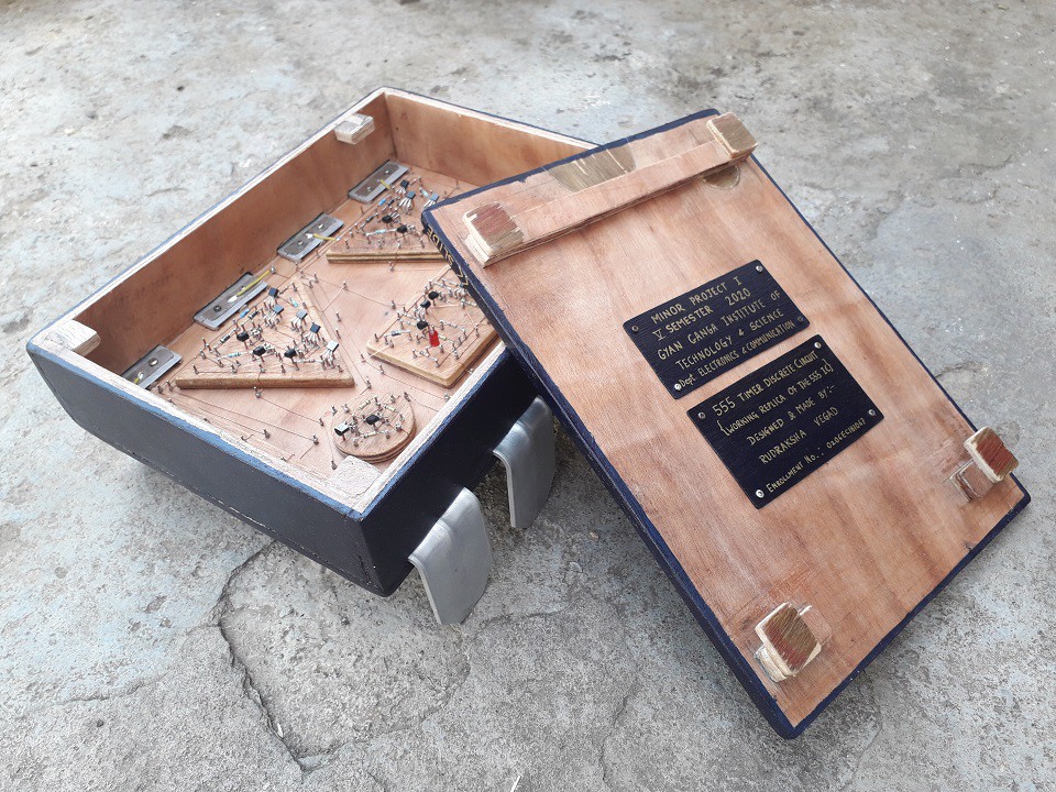
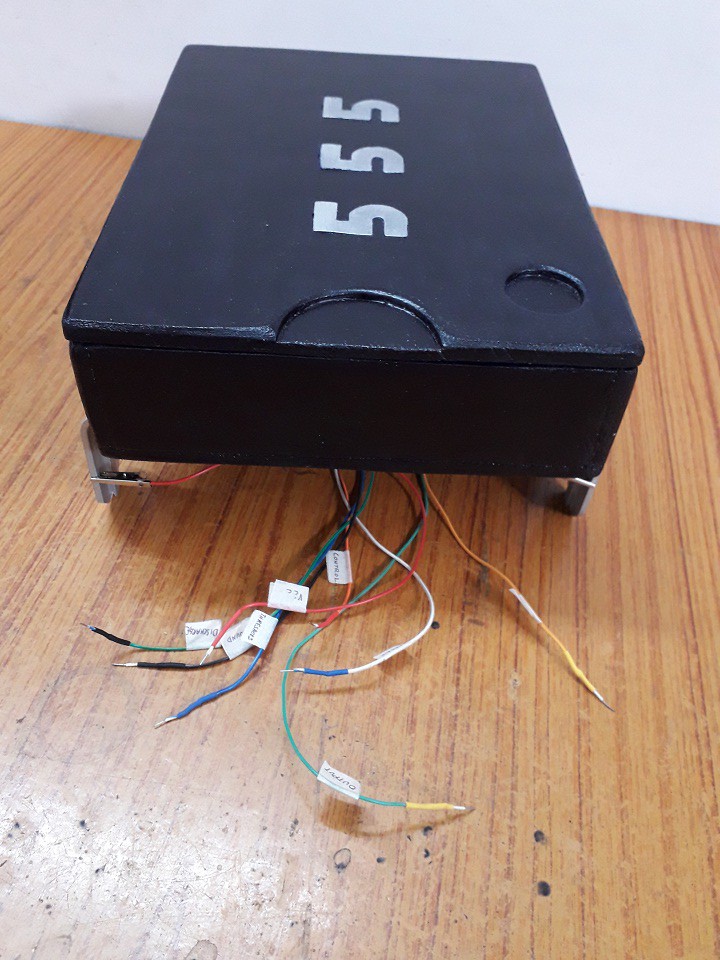
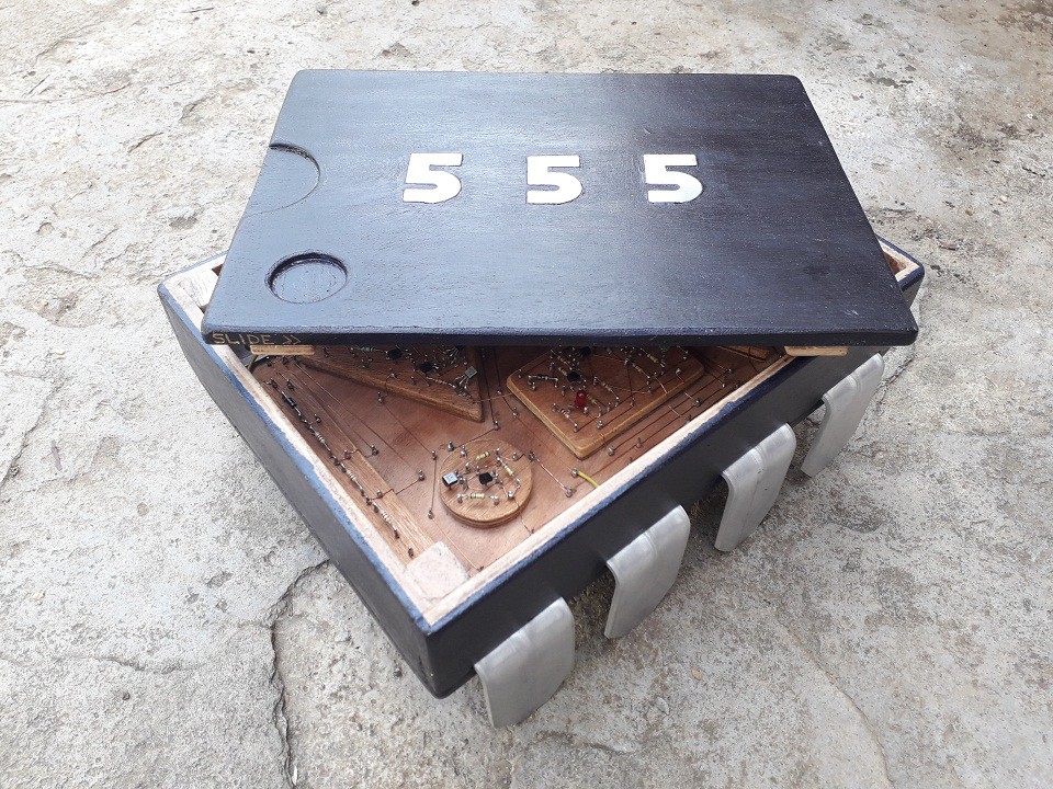
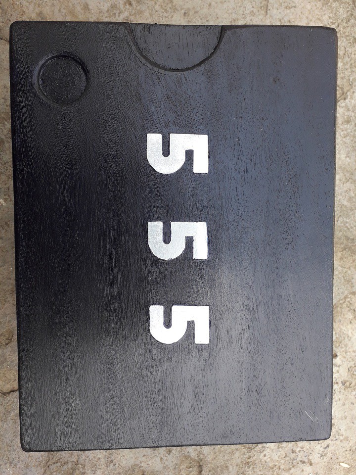
The Giant 555 Timer:
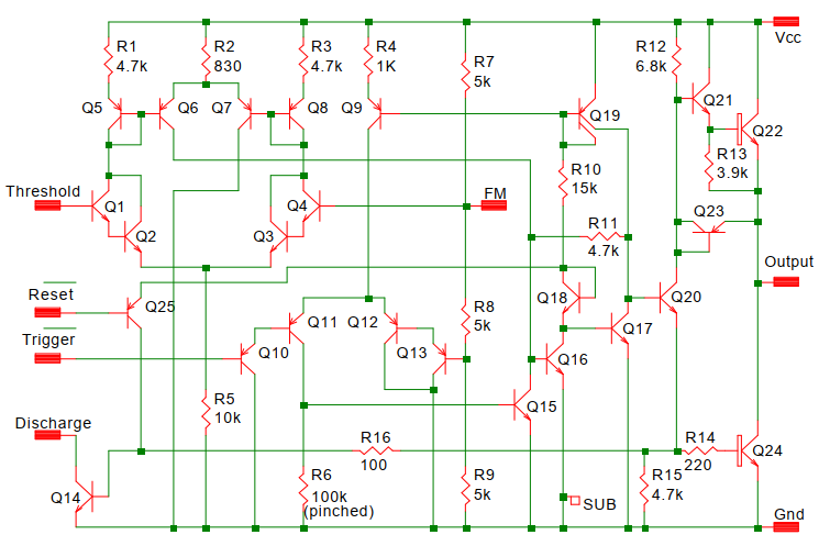
The main aim of making a discrete version of 555 is to understand how the 555 works at component level.
I was inspired to make this project from EEVblog 555 timer kit video.
I've always fascinated by OP-amps and what circuit is behind the op amps which make them a powerful component in electronics. The 555 IC contains two of these op- amps specifically voltage comparators which are similar but with a slight change in output stage.
Here I'll be listing the key details of making this project. Step by Step build guide and problems which i faced are given in the " build Instructions section." of this project page.
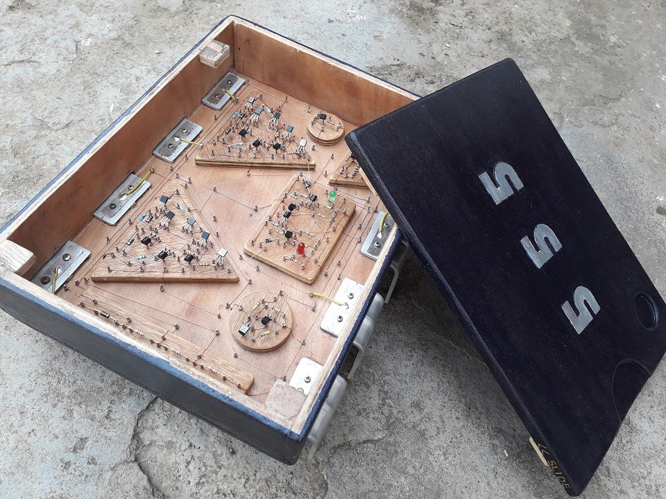
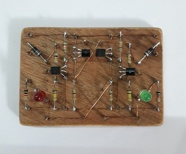
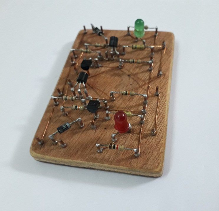
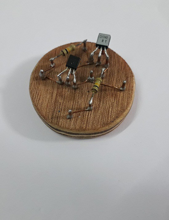
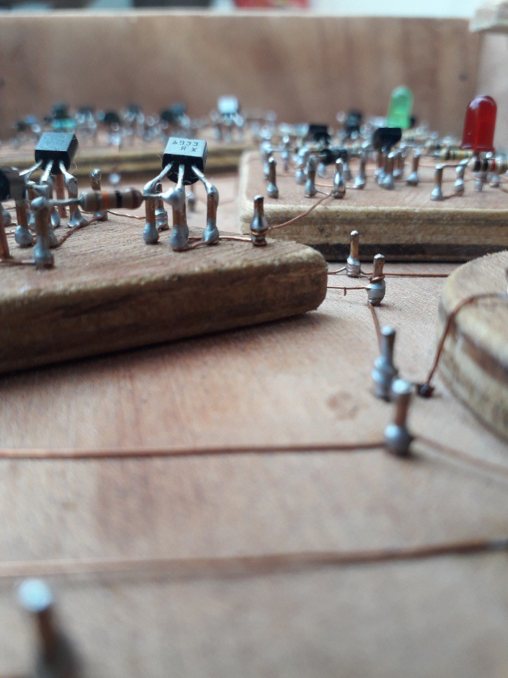
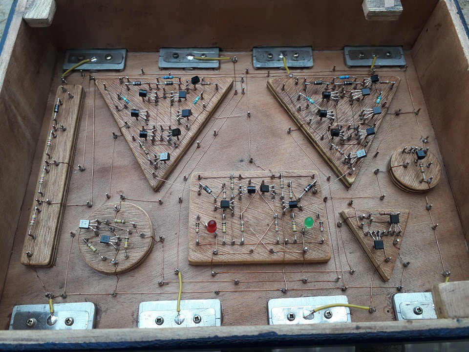
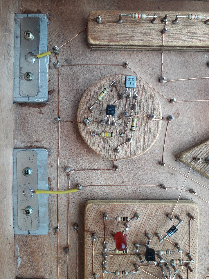
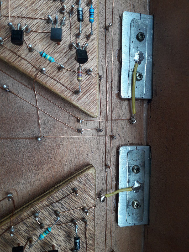
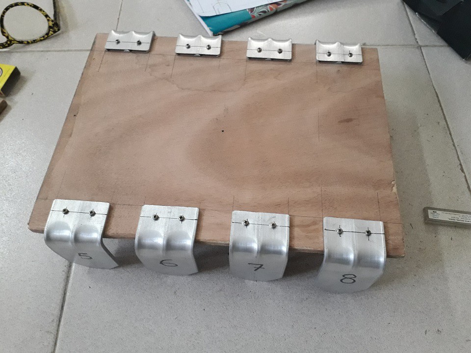
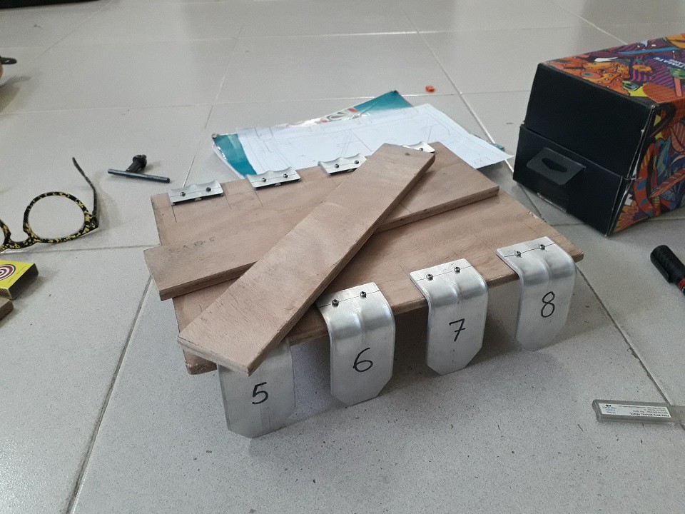
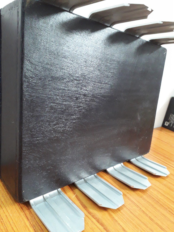
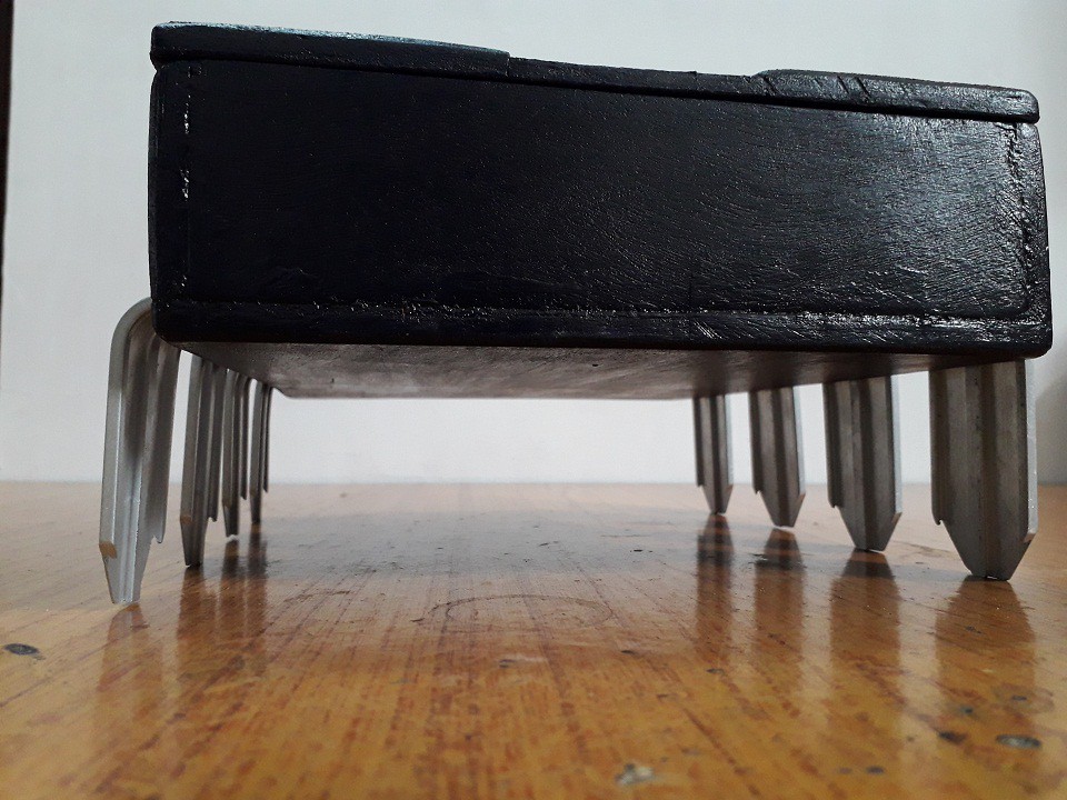
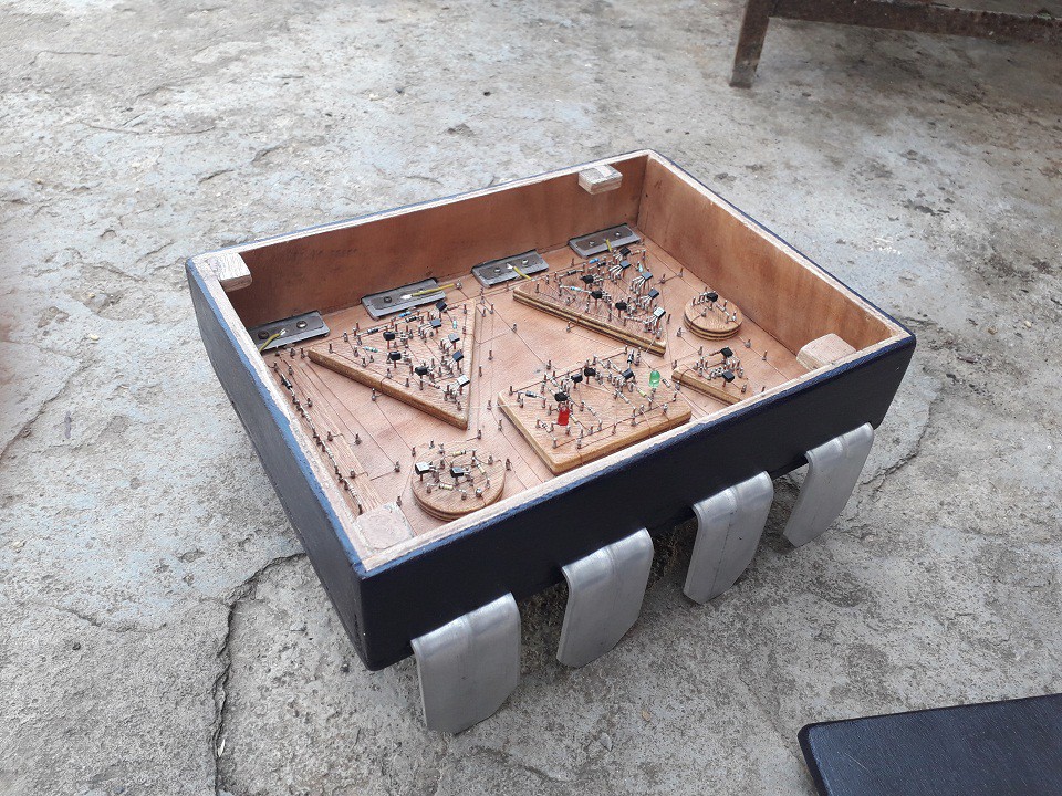
I Decided to solder the components in a traditional "real bread board" way - just hammering copper pins in a block of wood and soldering components.
This helps to see each and every connections as well as it looks really beautiful and interesting. I got this idea form Collin's Lab: The REAL Breadboard video
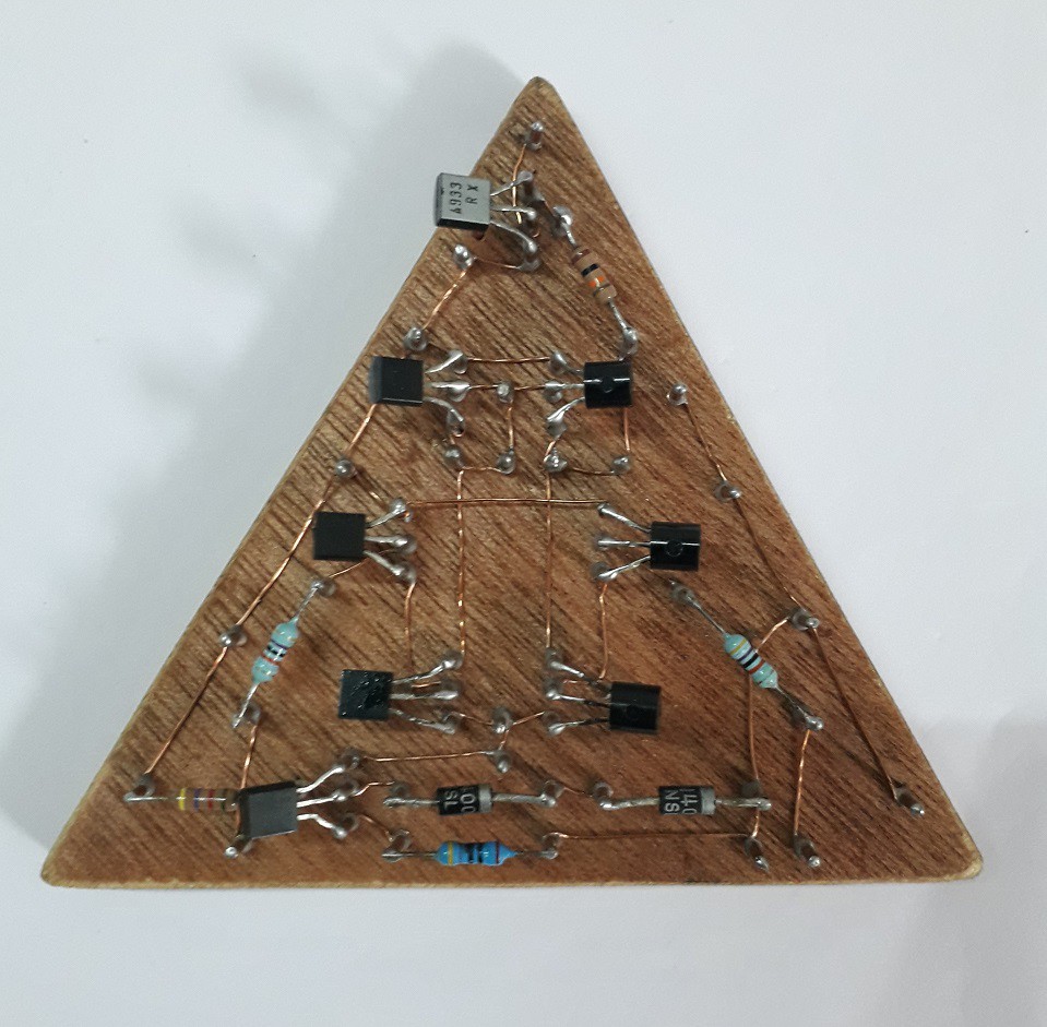
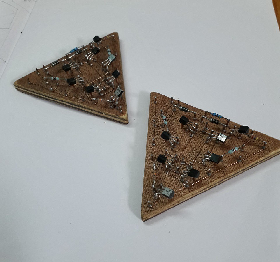
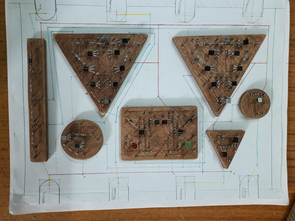
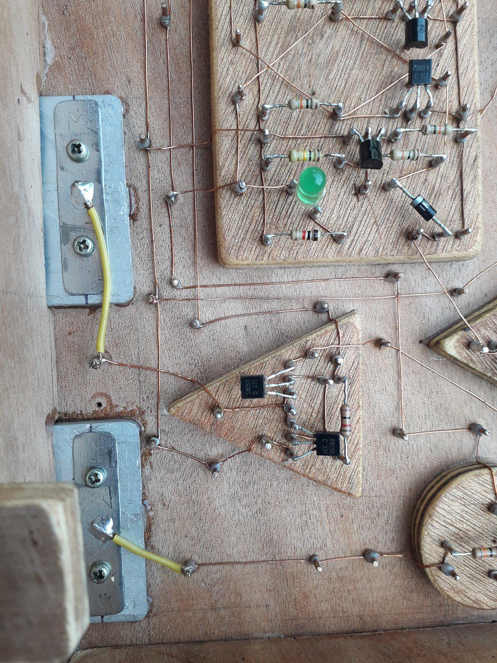
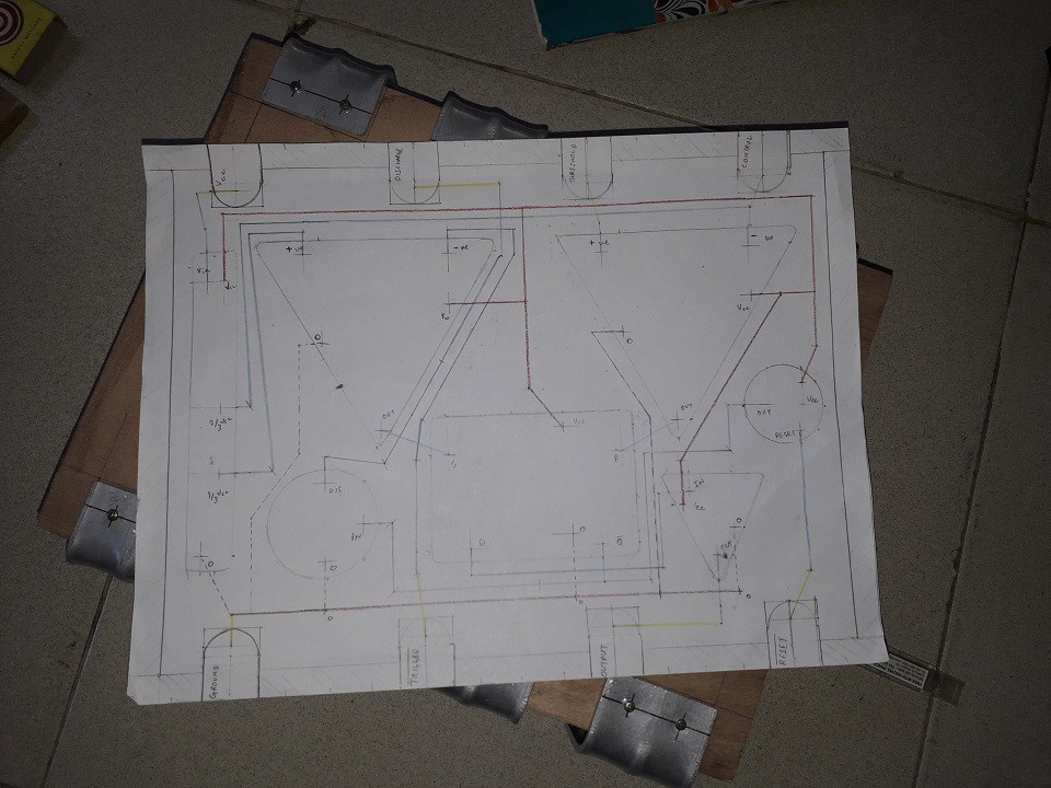
I Also made each block of 555 IC in the shape of schematic symbols.
For connecting all the components together I used ethernet cable's bare copper wire & for the jumper connections or isolated connections enameled copper wire
( magnet wire ) was used.
The soldering junctions are made of 1mm bare copper wire -cut into small pieces
and hammered them on wooden blocks as nails.
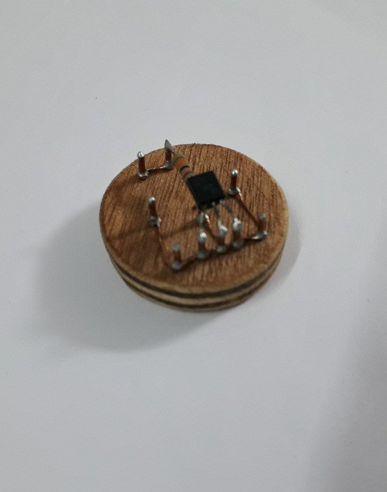
So to start off this project I decided to approach the 555's circuit in small parts, because it is always better to break up a big circuit in parts which helps troubleshooting easy and fiddling components around the bread board.
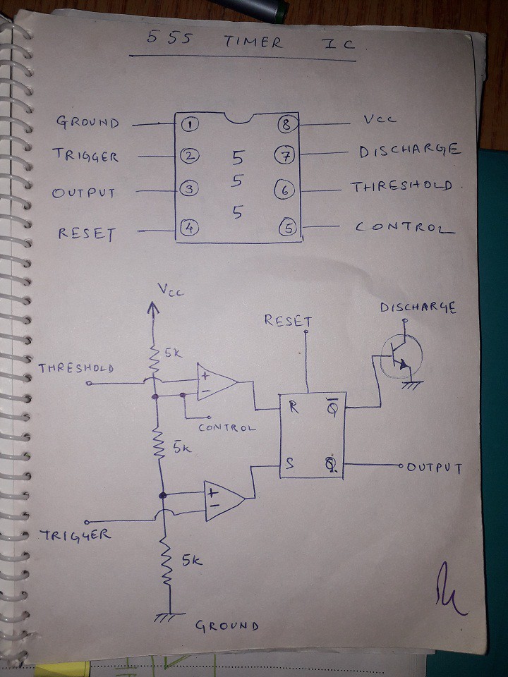
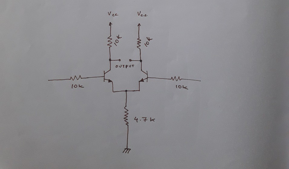
The voltage Comparator:
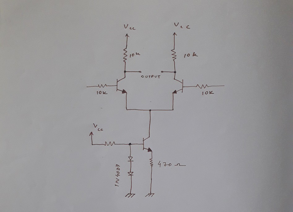
The most Interesting part of this project was learning and designing the voltage comparators used inside the 555 IC. Especially how a Differential pair works ,what is current steering.
I started from learning what are long tailed pairs which is the most important part for building the comparators by watching various lectures and tutorials on YouTube about long tailed pair or differential pair using BJTs.
I also learned the importance of constant current sink in a diff. pair and the use of current mirror to increase the gain of the diff. pair.
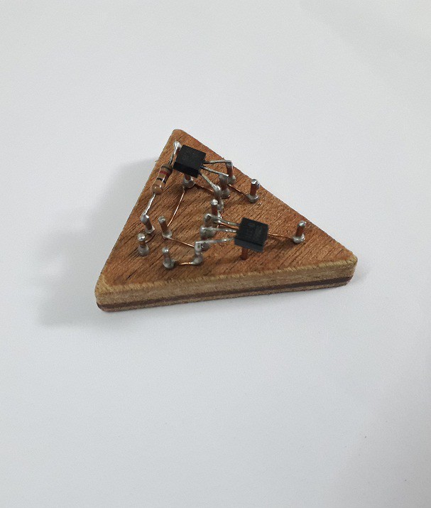
The SR Flip Flop:
Now for the SR flip -flop two transistor flip flop ( or NOT gate configuration ) is used with some additional output buffers to reduce the output impedance of Q & ~Q outputs.
The Output stage:
For the output stage ,in the original 555 timer there's totem pole configuration which is good but for me its a bit glitchy and not so good performing. So I used the good old push - pull stage for output buffer of the 555 IC which is for PIN no. 3.
The Reset Transistor:
Used a PNP BJT for the reset input.
The Discharge transistor:
A NPN Darlington pair for hard shorting to ground, single NPN was working but was having some issues in the A-stable mode.
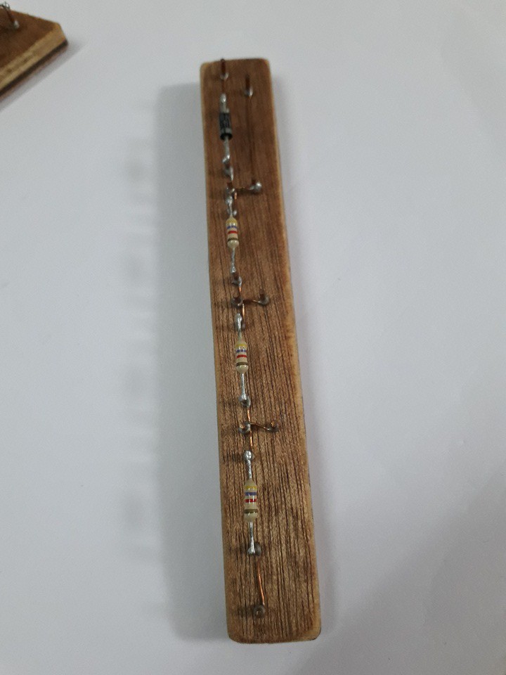
The Voltage Divider:
The Voltage divider is straight forward - used 4.7K resistors and a series diode protection for the whole circuit.
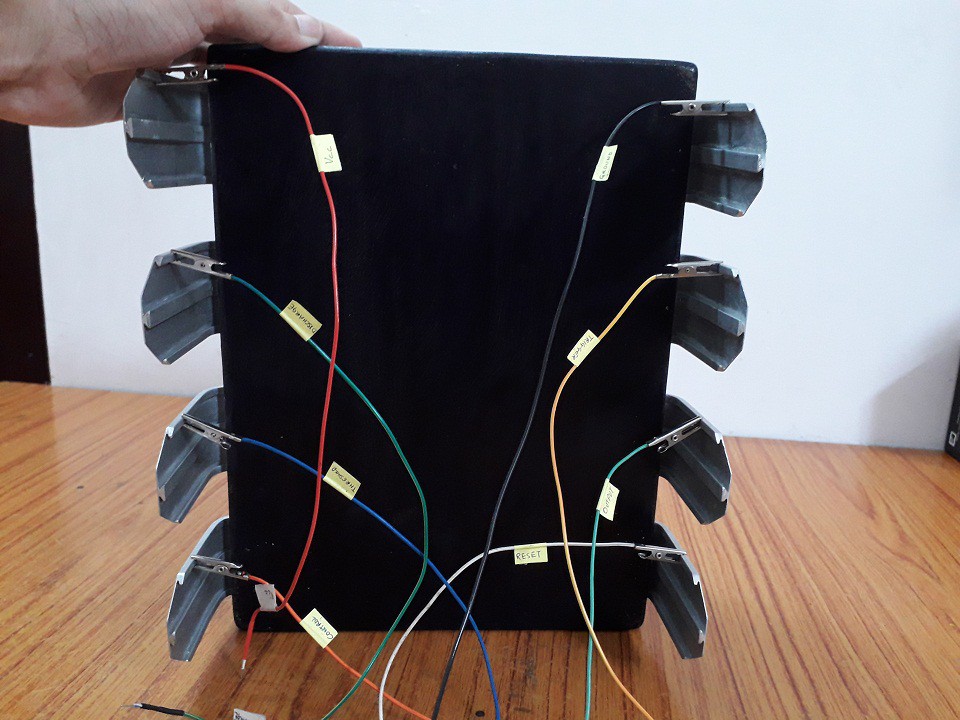
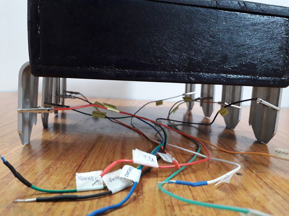
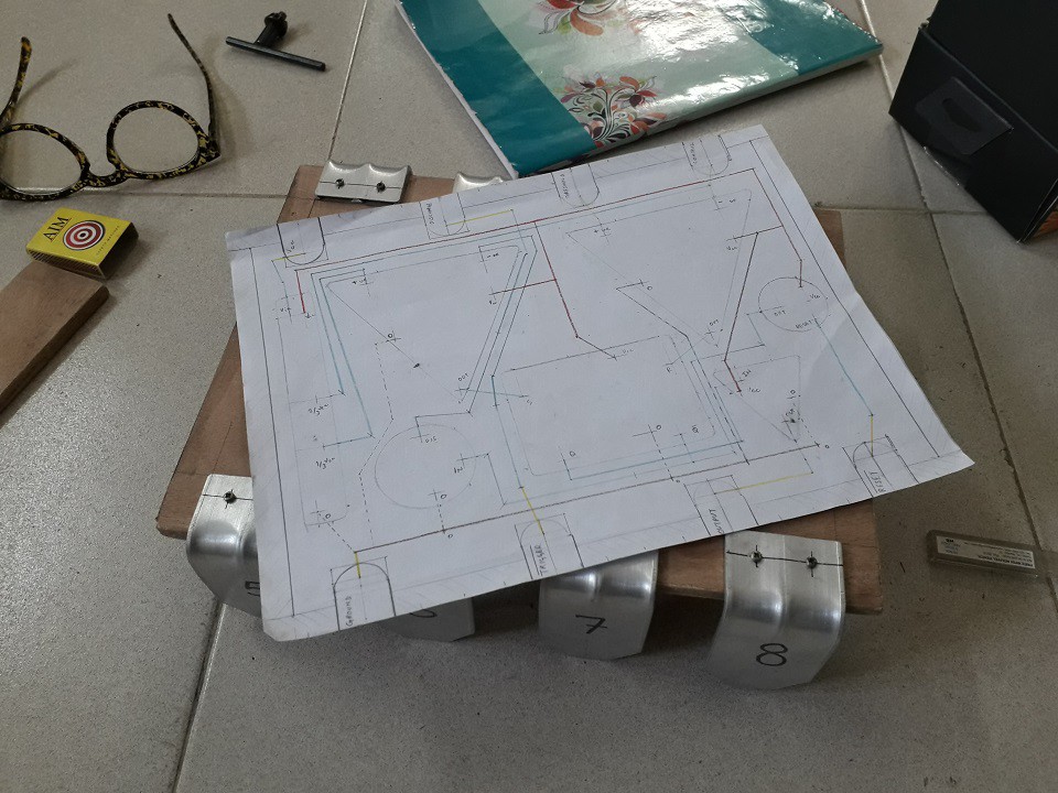
Finally the interconnection layout was planned :
The connections are made such that it correctly matches the pin configuration of the real 555 timer.
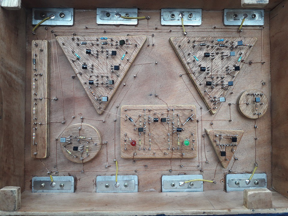
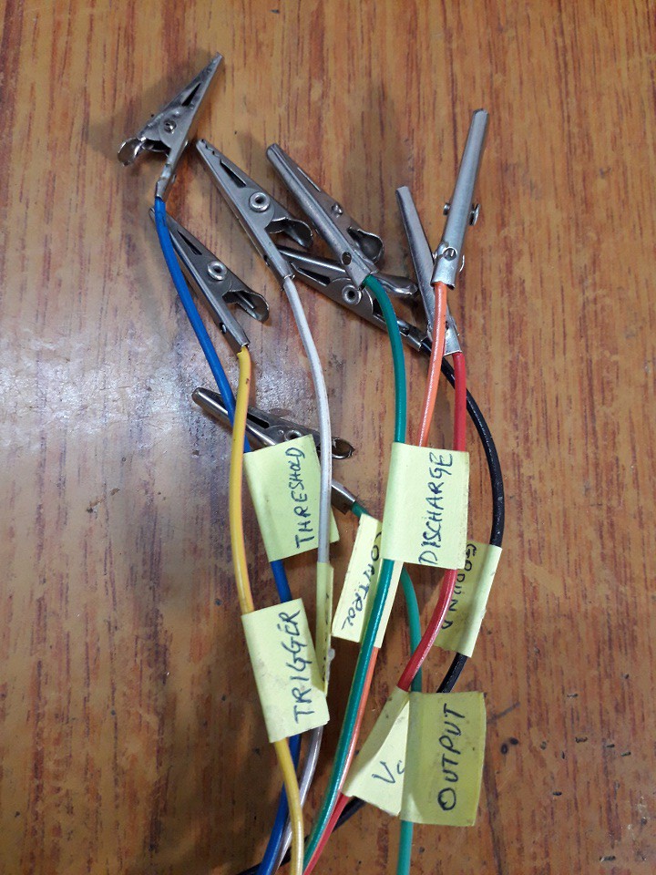
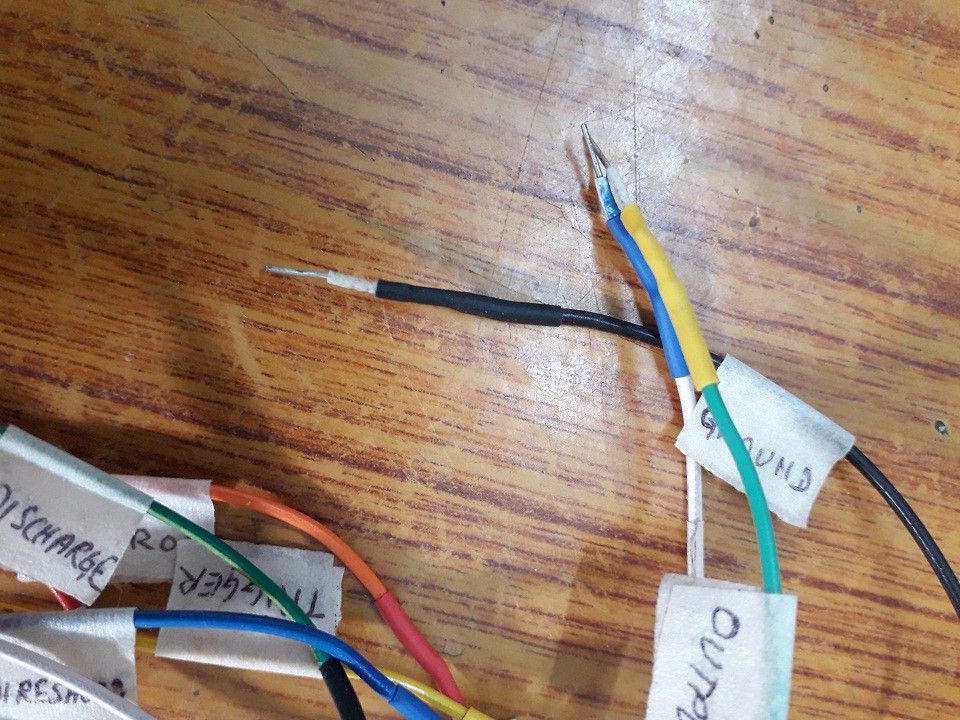
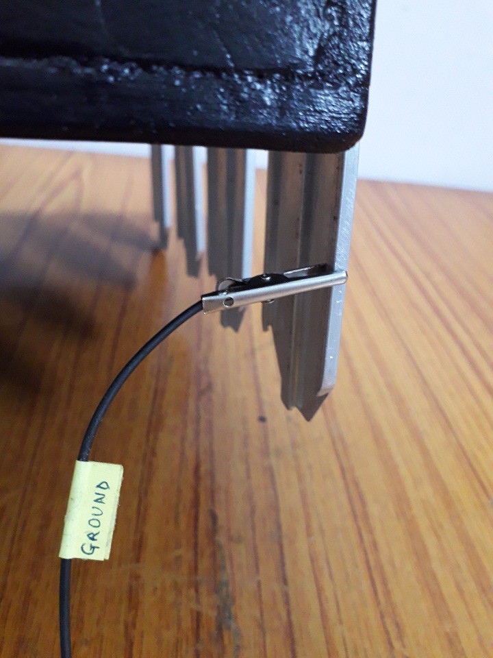
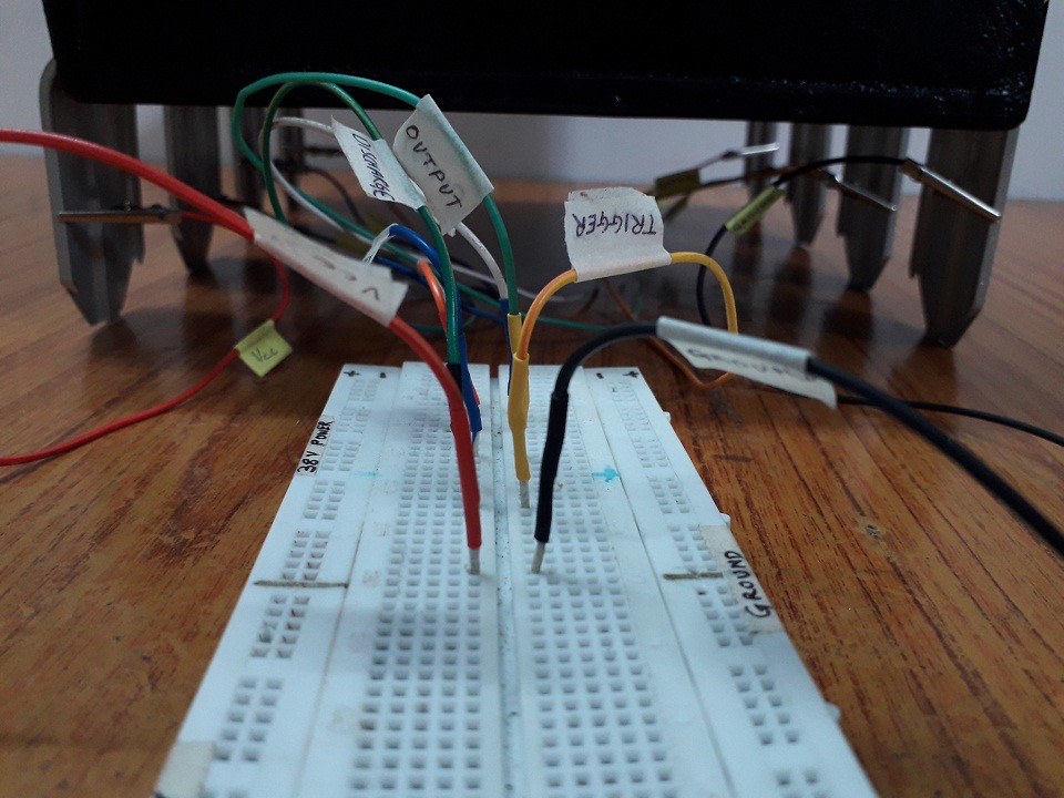
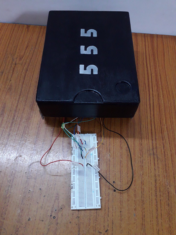
Connecting "Giant 555 Timer" to breadboard:
I made some alligator clips with pin markings to test it on breadboard.
Demonstration videos:
All detailed working modes with output signal on oscilloscope.
Video contents:
0:00 Build steps slideshow
4:20 Preparing to test it on breadboard
5:05 Working demonstration videos : Mono-stable, Bi-stable, A-stable modes


 Greg Duckworth
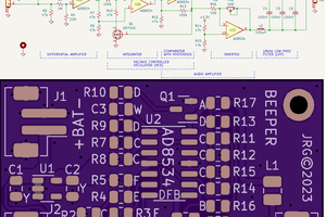
 CompuCat
 Frédéric Druppel
one of the best projects !