 Nick Bild
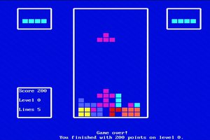
Screenshot of Vectron VGA Plus running a demo: 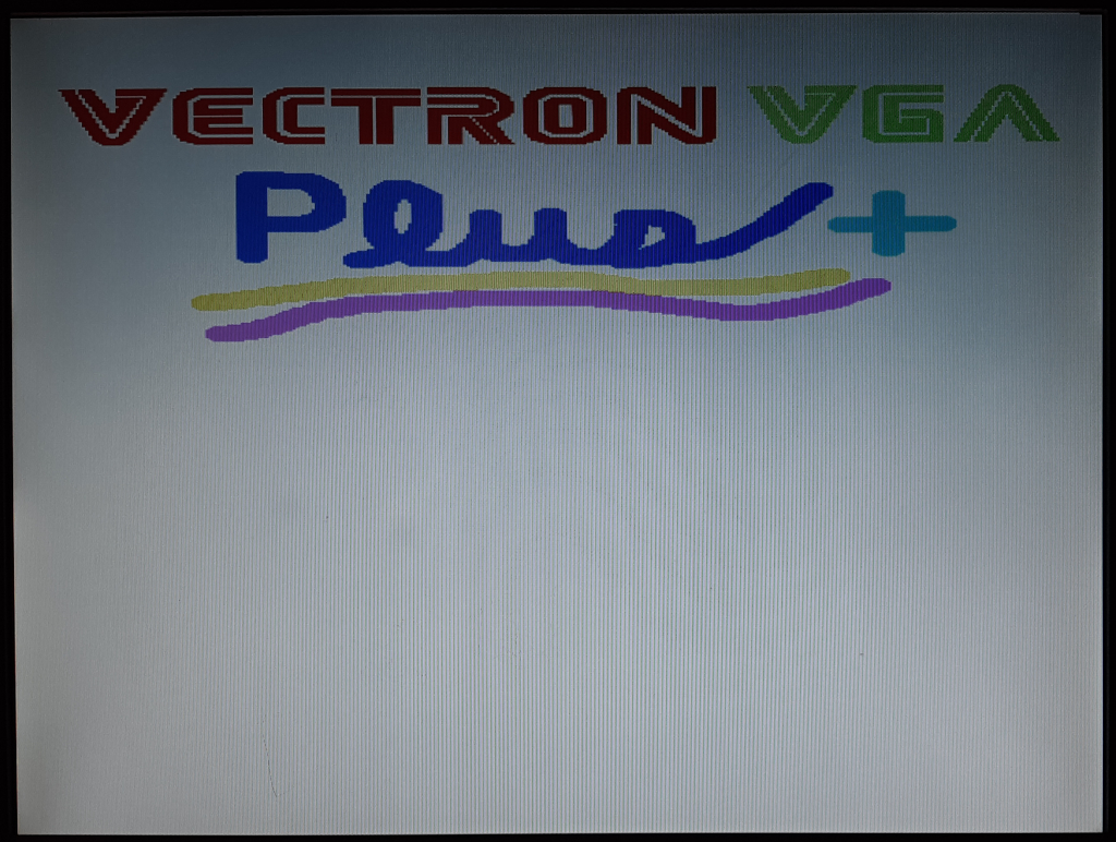
How It Works
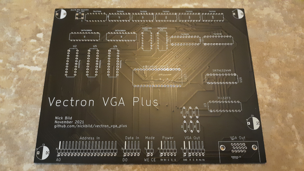
I previously built a massive 7400-logic based VGA generator called Vectron VGA. While it was a nice project to build, it is huge, and not very practical to keep around for use in lots of other projects. I built Vectron VGA Plus as a much smaller, simpler alternative.
The key change that simplified the design was to use more RAM and less logic. So, for example, instead of having counters and flip flops, etc. to time each horizontal sync, that logic is embedded in the data in memory. This new design was also used to create a PCB, and the KiCad files are here.
The general overview of the design goes like this: a 25.175 MHz pixel clock (divided in half by a flip flop) is used to trigger a chain of 4 bit counter chips. These counters form an address in memory, and bits from the data stored at that memory location represent red, green, blue, horizontal sync, and vertical sync. When the end of a frame is reached, magnitude comparators reset the counters, and it all starts over for the next frame.
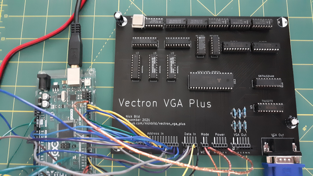
Of course you also need to get data in to the RAM, so there are some buffer chips and mode selection signals to allow an external device (e.g. retro computer or microcontroller) to take over bus control and write RAM as needed.
As I mentioned, the 25.175 MHz clock has been divided by 2, which yields a viewable resolution of 320 horizontal pixels. To keep logic simple, the vertical resolution is kept at 480 lines, technically giving an odd resolution of 320x480, but it is expected that in actual use, the external device is going to double up horizontal lines, giving a standard resolution of 320x240. 3-bit color was implemented, yielding a palette of 8 colors.
Since even non-visible screen regions need to be represented in the RAM (for blanking periods and V-sync/H-sync timings), RAM usage is higher -- 320x480 requires 210KB of video RAM (I used a 512KB chip that I had on hand, but a 256KB chip would be sufficient). That's a bit extravagant for the 80s-esque 6502-based retro computers that I build, but it's also, I think, within bounds for a pure retro device (as opposed to using a microcontroller or FPGA). In addition to the reduction in chip count, this design also pays off in flexibility; timings can be tweaked by adjusting the contents of memory, even after the PCB has been finalized.
Media
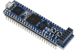
An Arduino Mega 2560 sending images to Vectron VGA Plus:
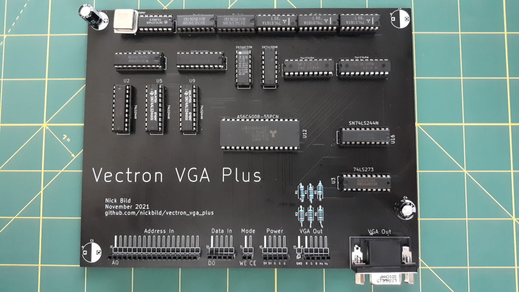
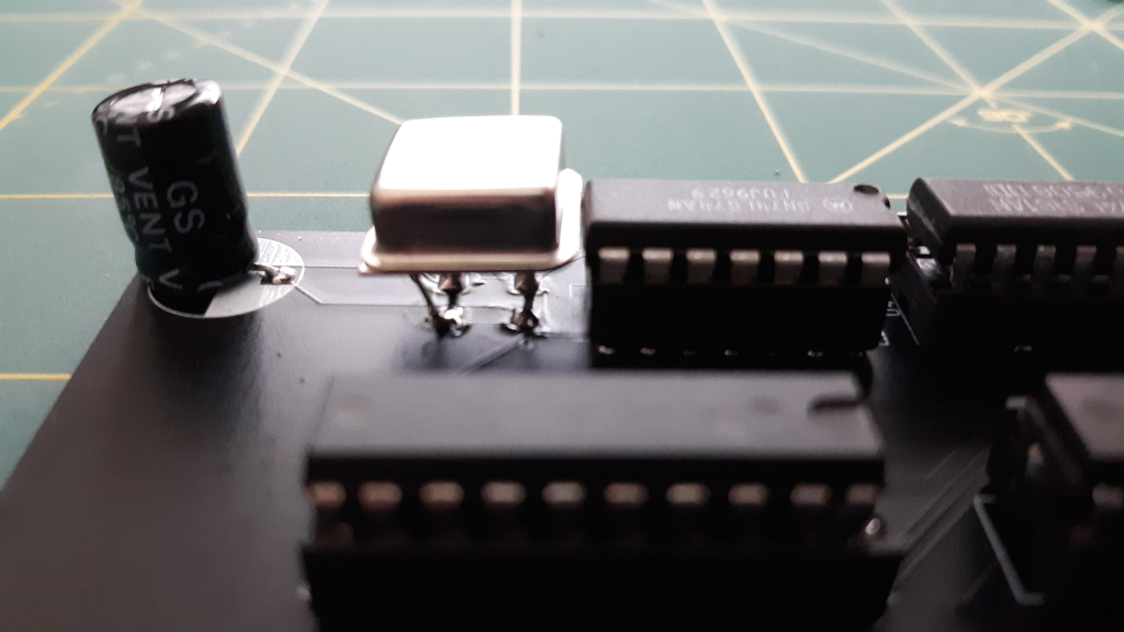
Oops! I picked the wrong footprint for my oscillator! Fortunately, I could still solder the pins to the pads.
Schematic:

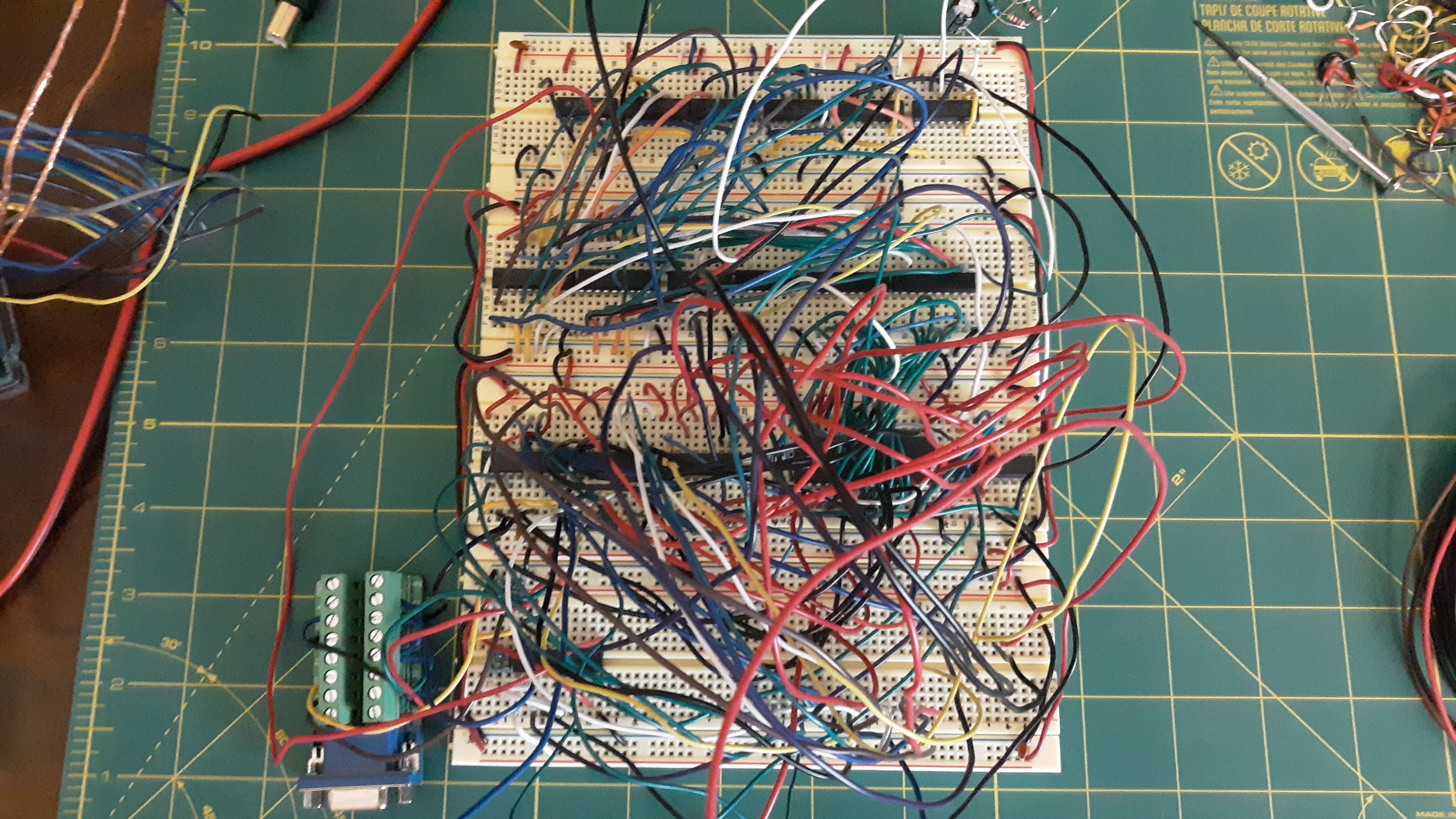
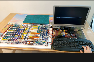
Breadboard prototype of circuit:
Bill of Materials
- 1 x 25.175 MHz oscillator
- 1 x 74LS74AN
- 5 x 74LS161
- 2 x SN74LS682N
- 1 x SN74HC32N
- 1 x 74LS04N
- 2 x SN74LS245N
- 4 x SN74LS244N
- 1 x AS6C4008-55PCN
- 1 x 74LS273
- 3 x 200 ohm resistors
- 3 x 100 ohm resistors
- 2 x 200 uF electrolytic capacitors
- 1 x VGA connector
- 36 x female header pins
About the Author


 Dave Henry
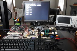
great looking project! looking forward to trying it out!