Close
0%
0%

urban-edc-flashlight

Multifunction flash light for everyday carry

Similar projects worth following
The purpose is to build a light with a feature set based on the RovyVon Aurora A8x Multifunction LED Keychain Flashlight but at a more customer friendly price tag.
The focus here will be on the electronics instead of the mechanics. I don't have the skills nor the tools to create a custom IP66 enclosure.
The flashlight is to be used in urban every day life environments. If your life depends on your flashlight then you'd better look elsewhere.

Commercial solution

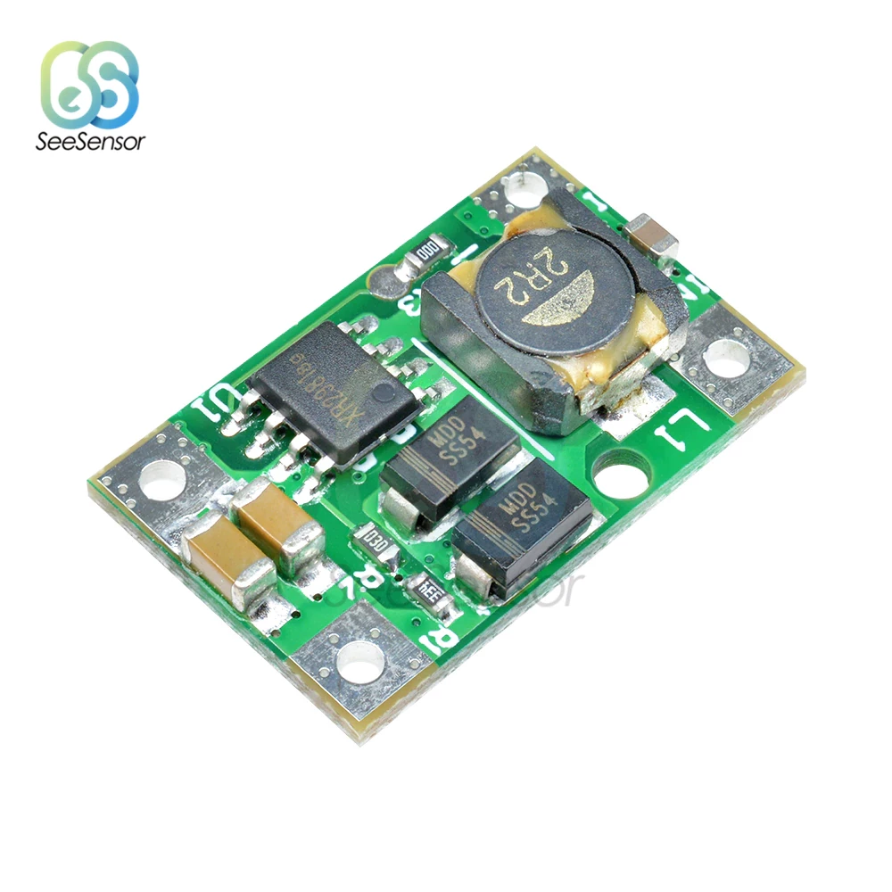
Emisar D4V2 : popular EDC-light, can be reflashed.  Open Anduril firmware available.

Features not to forget to be added

  1. Can be hung from a string
  2. low-voltage warning
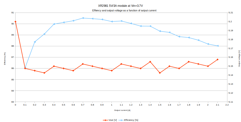
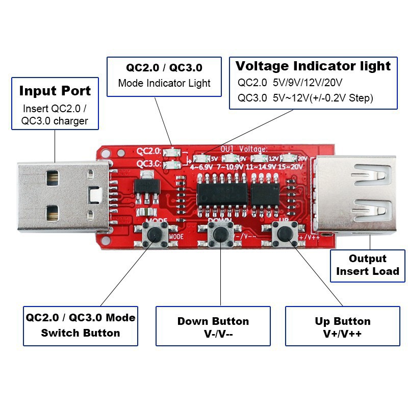
    1. measuring voltage using boosting trick of cyclotron-mini
    2. or ATTiny measures its own power supply voltage as on Konijntje-thermo-humi (no extra hw-required)
  3. Charging LED

Hardware

Firmware

RovyVon Aurora A8x User Manual.pdf

RovyVon Aurora A8x User Manual

Adobe Portable Document Format - 319.01 kB - 01/07/2022 at 13:12

Preview
Download

qc_charger.ods

Power efficiency measurement of TPS61088A module

spreadsheet - 27.64 kB - 12/10/2021 at 20:24

Download

XR2981-module.ods

Power efficiency measurement of XR2981 module

spreadsheet - 18.21 kB - 12/10/2021 at 18:56

Download

Xysemi_XR2981.pdf

Datasheet Xysemi XR2981

Adobe Portable Document Format - 677.46 kB - 12/07/2021 at 19:42

Preview
Download

  • ATTiny84A Low power mode

    Christoph Tack01/19/2022 at 20:53 0 comments

    Sleep and wakeup

    Mode with lowest power consumption is power down mode.  The MCU can be woken by e.g. a pin change interrupt.

    At wakeup, the interrupt handler is executed, then the code continues where it left of before sleeping.

    Pull-ups

    Pull-up settings remain valid during power down mode.  So you can leave out many pull-up resistors.

    Software reset

    The software reset is executed by first enabling the watchdog timer with minimal time interval, followed by running an endless loop.  The first thing the setup() function should do is disable the watchdog again.

    Peripherals

    Internal ATTiny peripherals can be powered down to limit current consumption.  Don't forget to re-enable them after wake-up or your code won't run correctly.

  • Secondary light source

    Christoph Tack01/10/2022 at 21:04 0 comments

    Ultra-violet

    With 30mA through the LED, there's enough UV-light to inspect your hotel bathroom when other lights are turned off.  The downside of this LED is the high forward voltage.  It's in the range of the Li-Ion supply voltage as it drops during discharge.  For the sake of circuit simplicity, we'll use 2 UV-LEDs in series and use a boost-converter to power them.

    RGB

    • WS2812B
      • Control by one GPIO, no PWM or large inductor needed.
      • VCC=3.5 to 5V : can be directly powered from the Li-Ion battery
      • provides many colors
      • MCU must run at ≥ 8MHz
      • tested and verified on PIN_PB1.
      • consumes 500µA to 1mA when LED is off, depending on power supply voltage

    Always ON LED

    • Lumileds Luxeon 3535L L135-L567003500000 : 3.1V/100mA

  • Debugging

    Christoph Tack01/05/2022 at 21:02 0 comments

    Serial output

    If you want to read the value of a variable inside your MCU, the easiest option is to just print it on the serial port.

    TX-pin is PIN_PA1.

    Calibrate your MCU-clock

    1. Set the fuse to enable clock output on PIN_PB2.
    2. Use a frequency counter (or an oscilloscope) to measure the frequency.
    3. When it's not correct you can adjust the frequency using the OSCCAL-register:
      void setup()
      {
          OSCCAL-=4;
      }
      

    Disabling RX

    void setup()
    {
        OSCCAL-=5;//999.178kHz
        Serial.begin(4800);
        //Disable Serial RX
        ACSR &=~(1<<ACIE);
        ACSR |=~(1<<ACD);
    }
    
    void loop()
    {
        Serial.print("Hello");
        delay(1000);
    }

  • Microcontroller

    Christoph Tack01/04/2022 at 20:57 0 comments

    For this a low power, low performance application.  My go-to microcontroller is the ATtiny84A:

    • Wide input voltage range (no need for 3V3-LDO when powering by Li-Ion)
    • Plenty of peripherals (I²C, SPI, timers,...)
    • built-in EEPROM
    • no UART (but SoftwareSerial possible)
    • enough GPIO
    • SOIC-package which is easy to hand-solder
    • Arduino & PlatformIO support
    • previous experience with AVR-family
    • 100nA shutdown current

  • Getting started with ATTiny84A on PlatformIO

    Christoph Tack01/04/2022 at 19:26 0 comments

    Tools

    • Development board.  I use the Konijntje-thermo-humi board from a previous project.
    • ISP programmer.  I use the Atmel AVRISP MkII

    PlatformIO setup

    1. Create a new project and select "Generic ATtiny84 (Atmel)".  The Arduino-framework will automatically be selected.
    2. Adjust the platformio.ini file:
      [env:attiny84]
      platform = atmelavr
      board = attiny84
      framework = arduino
      upload_protocol = avrispmkII
      upload_port = usb
      
      ; https://www.engbedded.com/fusecalc/
      board_build.f_cpu = 1000000L
      board_fuses.lfuse = 0x62
      board_fuses.hfuse = 0xD7
      board_fuses.efuse = 0xFF
      upload_flags =
          -B  ; bit clock needs to be slowed down (original=1) when underclocking the MCU
          10
      
      lib_deps =
          stevemarple/AsyncDelay @ ^1.1.2
          thomasfredericks/Bounce2 @ ^2.70
      
      ; FTDI TTL-232R-3V3-WE
      monitor_port = /dev/ttyUSB0
      monitor_speed = 4800
    3. Simply hit the "Upload"-button to program your device.

    That's it.  No makefiles, no menu configs.

    Remember to upload your code again after programming the fuses (if needed).

    Here goes the blinkenlight example:

    LED_BUILTIN = PIN_PB2

    #include <Arduino.h>
    
    void setup()
    {
        // put your setup code here, to run once:
        pinMode(PIN_PB0, OUTPUT);
    }
    
    void loop()
    {
        // put your main code here, to run repeatedly:
        digitalWrite(PIN_PB0, HIGH);
        delay(500);
        digitalWrite(PIN_PB0, LOW);
        delay(500);
    }

    framework-arduino-avr-attiny

    More info about the framework (and the pin numbering) can be found on:

  • LED driver

    Christoph Tack12/20/2021 at 20:58 0 comments

    Driver for main light source

    The selected light source is a 12V LED-COB panel.  There are not many circuit options to consider here.  A boost converter will do the job just fine.  In the current component shortage situation, we'll have to look for a solution that allows for multiple second source components.

    That brings us to the following:

    cdn.hackaday.io/images/3590361640031770457.png

    Pin list :

    1. SW : Switch
      1. AP3031 : 1MHz, max. 1.4A
      2. RT4533 : 1.1MHz, max. 1.2A
      3. FAN5333A : 1.5MHz, max. 1.5A
      4. MP302DJ : 1.3MHz, max. 1.3A
      5. MIC2291 : 1.2MHz, max. 1.2A
    2. GND
    3. FB : feedback voltage :
      1. AP3031 : 200mV
      2. RT4533: 200mV, RT4533A=300mV
      3. FAN5333A: 110mV
      4. MP3202 : 104mV
      5. MIC2291 : 95mV
    4. CTRL : enable pin: high = ON
    5. OV : over voltage protection
      1. AP3031 : max. 17.5V
      2. RT4533=36V
      3. FAN5333A, no over voltage protection, only 15% over current protection
      4. MP3202 : 28V
      5. MIC2291Y : not present
    6. VIN : input voltage
      1. AP3031 : 2.7V→16V
      2. RT4533: 2.5V→5.5V
      3. FAN5333A: 1.8V→5.5V
      4. MP3202DJ: 2.5V→6.0V
      5. MIC2291 : 2.5V→10V

    Sources :

    • AP3031KTR-G1 has a 50µA quiescent current (CTRL=0V), so an external FET will be needed.

    • RT4533GJ6 : 300nA quiescent current (EN=0V).  Sold out Digikey end of 2021.
    • FAN5333ASX: 100nA quiescent current (/SHDN=0V), but 1µA switch leakage? (2023: obsolete)
    • MP3202DJ : 100nA quiescent current (VEN=0V)
    • MIC2291Y : 100nA (VEN=0V)

    Driver for secondary LEDs

    The UV-LED has a forward voltage of up to 3.8V, while the Li-Ion battery is only 3.6V.

    Reusing primary LED driver

    We can cut costs by reusing the LED-driver for the main LED-string.  The sense voltage is 200mV for the AP3031, which is quite a low voltage.  This enables us to use NMOS-FETs to switch the LED-strings without need for gate bootstrapping.

    VLED = VOUT of the AP3031, the resistors are the Riset for each LED string

    By the arrangement of the sense resistors as shown in the picture, we can make each LED string work with a different LED-current.

    Design consideration : Linear LED driver

    We need a sense resistor in series with the LED.  This causes an extra voltage drop, which requires a higher supply voltage.  The 5V booster could be used to provide power for the linear LED driver.  It's there already anyway.

    The problem with this approach is the rather limited efficiency, both of the 5V booster for such low currents and of the nature of the linear LED driver itself.

    An LMV321A opamp-current source with an FDV301 drive transistor and with 100mV over the sense resistor doesn't allow for the full 30mA output of the LED.  At least 3.4V is needed.  To be able to dim it, independent of the supply voltage, an extra voltage reference is needed.  This is becoming a bulky circuit.

    Led driver with low sense voltage and dimming independent of power supply voltage

    The AP2502 could be used instead, but unfortunately it's a single source component.

    As it turns out, this circuit will cost more (both in money and PCB-area) than using the AP3031 with two UV-LEDs.

    Design consideration :Switching LED driver

    See #TritiLED for more info.

    cdn.hackaday.io/images/3356781640341836855.png

    This is the basic circuit of the switchable LED driver.  NMOS-transistor M1 conducts, causing the current through L1 to rise.  When M1 stops conducting, L1 will dump its magnetic energy inside the (blow-back) LED D1.

    A trade-off has to be made between the switching frequency and the inductor value.  Smaller inductors are cheaper but require higher switching frequencies, which the MCU might not be able to deliver.

    This circuit has limited dimming range.  The pwm-resolution is 0.125µs.  The maximum ON-time is around 12.5µs (50mA peak, 4V power supply, 1mH inductor).  Which means we have a dimming ratio of only 1:100. 

    The ON-time regulation is very tricky in this circuit.  If the ON-time is too long (software bug or glitch), we'll end up blowing up the mosfet and the inductor.

    As a result this circuit...

    Read more »

  • Charging output

    Christoph Tack12/07/2021 at 20:02 0 comments

    As a power bank, this device should be able to supply 5V/1.5A, because that's what each of my tablet and phone are drawing during charging.

    Dedicated power bank ICs exist that incorporate a boost converter and battery charging and protection circuitry (Thinkplus MP5043/MP5045, Hotchip HT4936S & PB0059E, Injoinic IP5306).  These don't need many external components.  The main drawbacks are their limited output current capability and they turn off when the output current is too low.

    Another option is to design our own PCB using DC/DC-converters available : FeelingTechnology FP6276, FP6293, FP6298 or XYSemi XR2981.  Designing our own power supply board would take more time.

    Option 1: 5V/3A boost converter

    AliExpress 5V 3A DC-DC Step Up Power Module : €1.03/pce

    XR2981 module (cdn.hackaday.io/images/7300101638905789058.jpg))

    Uses Xysemi XR2981 boost converter., can also be found as H&Msemi HM9228B (hmsemi.com)

    • A TPS2514 will be needed on the USB-data lines to tempt the devices into drawing 1.5A instead of the normal 500mA.
      • Tablet : with tps2514 : 1.35A, without : 0.476A
      • smartphone (after a few seconds) : with tps2514 : 1.18A, without : 0.457A
    • The no-load input current is 150µA (at Vin=3.7V).
    • There seems to be very little filter capacitance on this board.  Ripple will likely be quite high.
    • The schottky diode has a Vf of 335mV at 1A and 359mV at 2A.
    • Inductor Rdc = 11mΩ
    5V output is actually 5.15V (cdn.hackaday.io/images/6733581639160347879.png)

    The measurement stopped at an input current of 3.5A, which was the maximum for my lab power supply.

    Option 2 : Qualcomm QC2.0/3.0 Fast charge module TPS61088A

    AliExpress TPS61088 Boost power module : €2.21/pce

    TPS61088A module (cdn.hackaday.io/images/4184451638906752621.jpeg)

    This module is more expensive, but it has the potential of faster charging by boosting the USB-voltage to 12V:

    • 5V/3A : a Blackview cellphone and Samsung Galaxy tablet settle for this mode, drawing 5V/1A.
    • 6.2V (=QC3.0) : used by cellphone BQ Aquaris X Pro
    • 9V/2A
    • 12V/2A

    The no-load current is 548µA with a supply voltage of 3.7V.  The EN-pin of the TP61088 is hard connected to VCC.  Even disabling the TPS61088 would still leave us the 200µA current draw of the FP6601Q.

    UVLO falling is 2.4V after which 0.5A is drawn.  If the input voltage rises again above 2.6V, normal operation is resumed.

    The TPS61088 is a synchronous boost converter, which minimizes losses that would otherwise be caused by the schottky diode.  There's also a larger inductor used here, which probably has a lower Rdc than the one in the 5V/3A-module.

    The measured efficiency matches the TPS61088A datasheet very well.

    Efficiency after correcting for resistive losses in cables and in the QC-selector module (cdn.hackaday.io/images/5690061639162162726.png)
    Measurement setup (cdn.hackaday.io/images/3155791639167441265.jpg)

    To be able to test it with an electronic load, I ordered a QC2.0/QC3.0 tester (AliExpress QC2.0 tester : €3.53/pce).

    (cdn.hackaday.io/images/1161241638907139365.jpg)

    A better USB tester is the Fnirsi FNB38.

    Another option is the Lithium Battery Charging and Discharging TYPE-C Integrated Board PD Bidirectional 18W Fast Charging Mobile Power Supply Bank.  It uses an unknown IC.  Idle current is unknown as well.  Support for QC3.0 and USB-PD 3.0.

  • Main light source

    Christoph Tack12/06/2021 at 19:15 0 comments

    The light will likely be used to light from close range (i.e. lighting a dark room, the inside of a cabinet or the underside of a car), similar as an LED inspection lamp.  I see less used for pointing a bundle of light at faraway objects (i.e. to draw attention, see where you're going at higher speeds such as a bike light).

    So we'll need a wide angle of light instead of a narrow beam.  That's why we'll use a COB-LED panel instead of a LED-STAR with a lens.  It leaves us the added benefit of lower cost.  COB-LED panels are very efficient.  The heat is spread over a large surface area, so a heat sink might not be needed (at least, that's the goal).

    Option 1 :  "4W" LED-COB panel 50x20mm

    AliExpress "Festoon light 12V" : €0.84/pce

    As the housing shouldn't be longer than a 18650-cell, this panel fits nicely.  The cool-white LEDs are generally more efficient than the warm-white version.

    LED voltage is "12V", so a boost-converter can be used to power it from a 4.2V Li-Ion battery.  The forward voltage is 10.1V at 300mA, 9.6V at 250mA.  The maximum current for this module without heat sink is 250mA.  The temperature rises by 45°C above ambient then.  This has been measured with a thermo-couple stuck to the backside.

    It would be more correct to rate this LED-COB panel at 2.5W instead of 4W.

    The 20Ω series resistor needs to be replaced by a 0Ω-resistor.  The resistor can't handle the power at a 300mA LED current (an 0805 resistor is not rated at 2W) and when powered by a LED-driver, this resistor isn't necessary anyway.

    36LED version ordered (https://cdn.hackaday.io/images/4952961638818551331.jpg

    The two-sided tape has been removed because it impedes the heat flow.  Two-sided heat transfer tape exists, but it certainly isn't cheap.

    Option 2 : "3W" LED-COB panel 60x8mm

    AliExpress Sumbulbs Official Store : €1.03/pce

    All LEDs seem to be in series in this panel.  The LED-voltage is about the same as a Li-Ion cell.  A boost and buck converters can't be used with a single panel.  We can put two panels in series and use a boost converter. 

    The panels could be mounted on touching surfaces of the housing to get an even wider light angle.  The two mounting holes allow for easy mounting.

    Some measurements:

    • Forward voltage : 2.8V (at 650mA)
    • Maximum current : 650mA without heat sinking the temperature settles around 56.5°C.  For that measurement, a thermocouple has been stuck to the back of the COB-panel.

    without additional heat sinking, power consumption is only about 1.8W (maybe 2W if you allow for a higher temperature)

    Once again, it would be correcter to advertise this panel as 2W instead of 4W.

    Conclusion

    Option 1 is preferred because of the lower current and higher forward voltage, this makes it easier to design an efficient and reusable (for other projects) LED driver. 

    The only issue that needs to be solved is the mechanical attachment.

View all 8 project logs

Enjoy this project?

Share

Discussions

Similar Projects

Does this project spark your interest?

Become a member to follow this project and never miss any updates