 Andrea Piccinno
Measurements & design approach
There are different ways of taking proper measurements before modeling the parts, the important is to avoid as much as possible to go by "trial-and-error" because well, no one wants to waste material and time when 3D printing.
In my case I went for photogrammetry, meaning that with about 50 pictures of my body I created a 3D mesh of myself and used it to model around it.
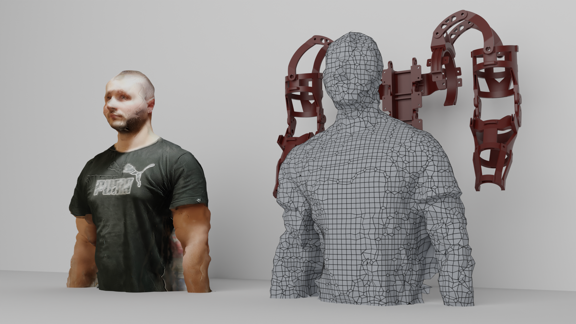
Of course, the mesh is not super accurate in details but all I cared about was the sizes and for this it's been perfect. No need of going to a 3D scanner which is way more expensive for example.
For some pieces this approach has been enough to achieve successful results at first print, for other no, obviously.
Apart from modeling the pieces, obviously some preliminary calculations have been done to determine a proper dimensioning and design for each piece. Given the current stage of the project, most of the calculations have been analytical (either handmade or with Excel tools) taking into account a proper safety factor.
A choice of good and reliable material brand providing accurate mechanical properties have been also very important in the process, as well as good print settings and the choice of color (yes pigments have a great impact on plastic’s mechanical properties, that’s why my whole exoskeleton is red 😉)
Arm piece
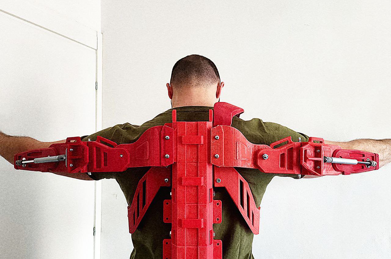
First piece to be sketched/designed has been the arm (bicep + forearm).
Took me a couple iteration to get to the right design having a proper comfort but the result was quite good.
I had a couple ideas for the elbow joint, but I found a simple offset ball joint to work properly for the aim with a good compromise of stability and freedom of movement.
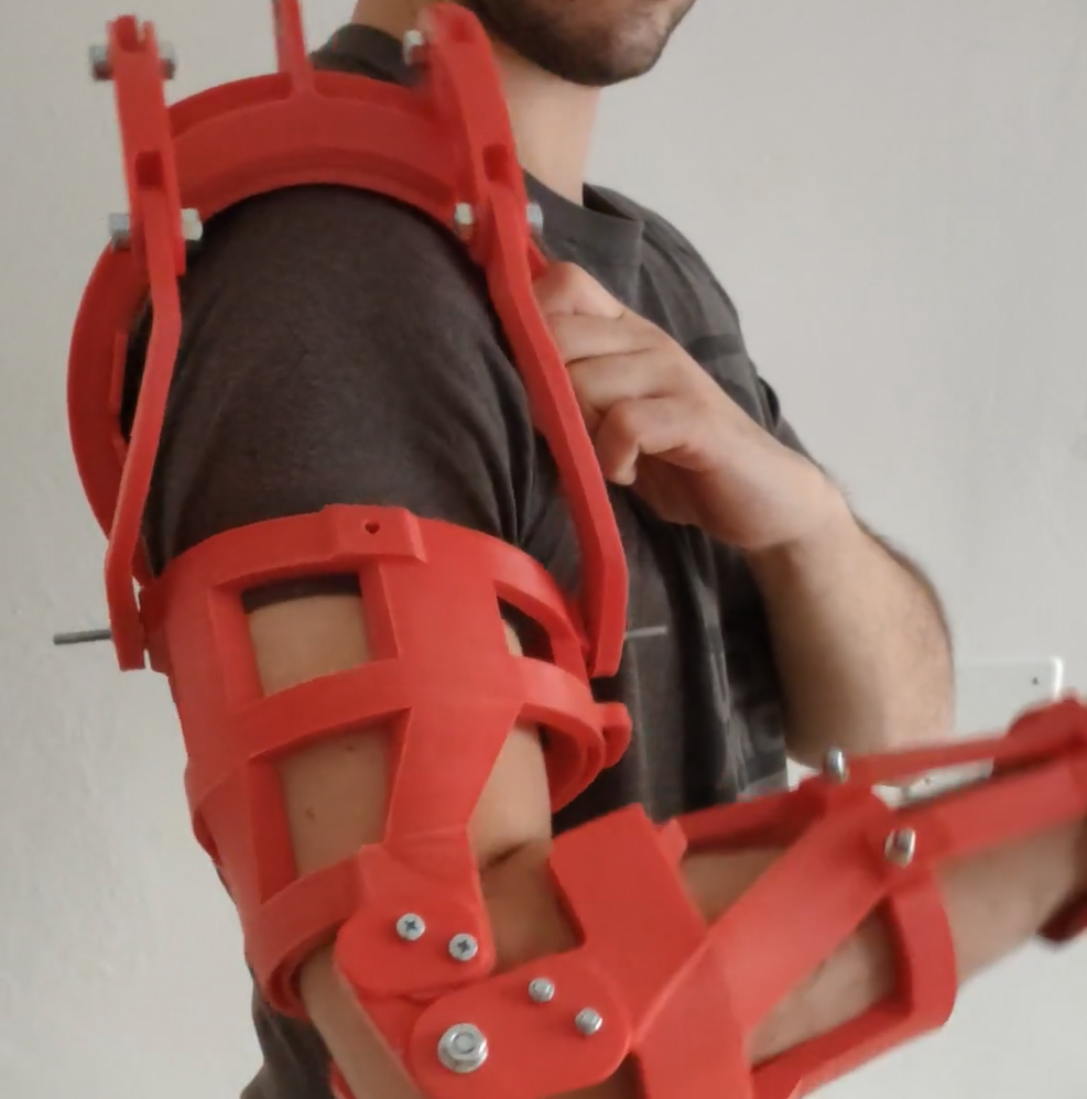
The whole arm is constituted of a hollow frame in which resistance bands will be added in a pattern very similar to our muscle structure (of course much more simple than that) in order to aid arm flexion or extension, depending on the pattern chosen.
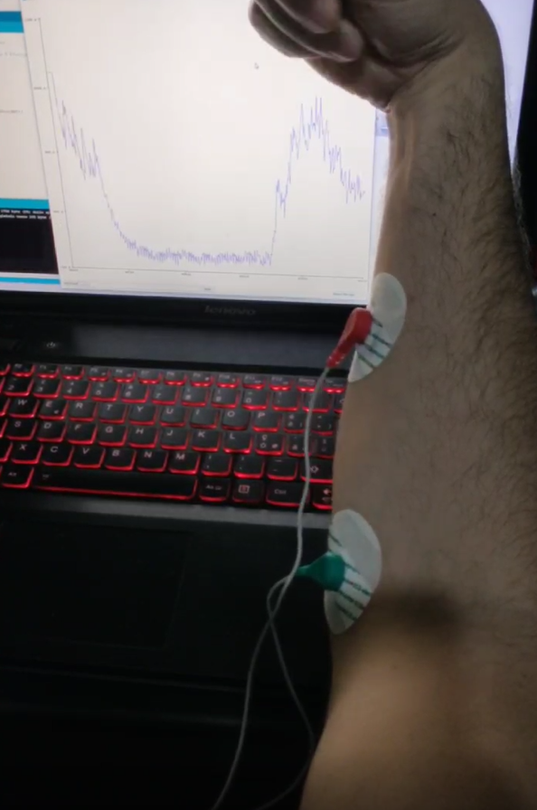
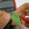
After this initial passive concept, nylon bands will be added in the frame and pulled by a high torque motor placed with appropriate path on spine or shoulders. Here is as example picture with a simple switch and a brushless 24V motor.
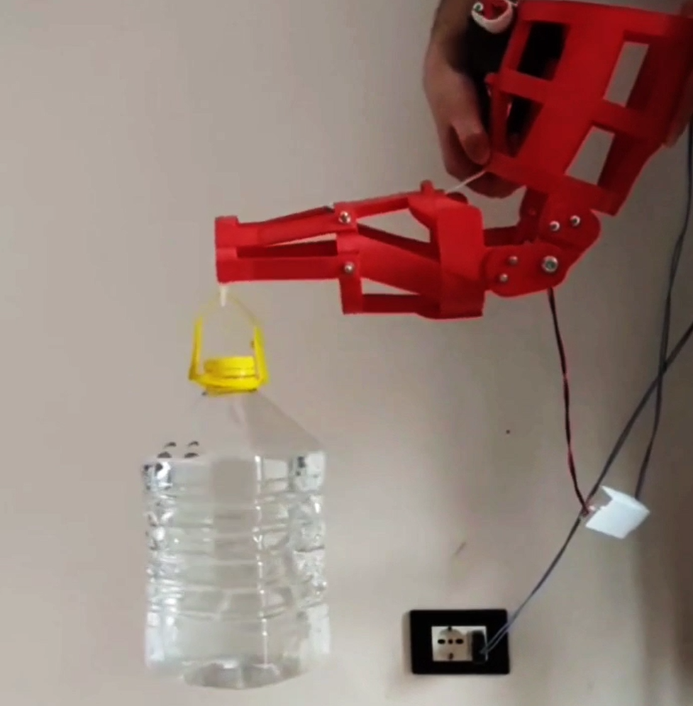
The reason I went initially for this concept is to avoid placing motors on the elbow, increasing the overall envelope and impacting the arm frame resistance and also penalizing the overall look. Drawbacks of this solution might be the high friction generated by the resistance bands path but, given the frame structure, an alternative design could be quickly implemented after initial full test.
Boots & legs
Boots are going to be the component taking the overall load from the full exoskeleton at the end, so I decided to add that bit of "push" to make it easier to walk. A bit of geometry, the right printing direction/settings for the different pieces and with a couple of gas springs I came up with this design which gives about 250N push at the heel.
Proportions have been accurately chosen in order to guarantee a good compromise between performance, push force and “walkability” and I decided to patent this whole piece since it’s one of the core ones of the whole concept.
Pivots for the gas springs can be moved and arranged properly (based on some geometric constraints equations) in order to change the maximum plantarflexion angle or the push force at the feel.Right after the foot, I designed the knee and leg piece in order to have the full lower limbs.
Knee piece uses similar gas springs to the one used for the boots. The overall design is very similar to commercial knee braces (with some features to increase resistance of the 3D printed piece) while the flexion/extension support is given by gas springs of 100N each, giving a total support at the knee of about 15Nm.
The choice of linear “actuation” (gas springs) has its reasons: mainly the easy availability (they are furniture gas springs which come...
Read more »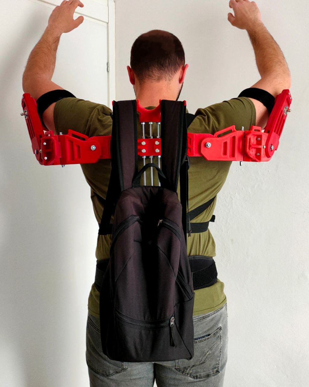


 Johannes Hassler
 Chad Paik
 Jason Bender
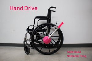
 Kate Reed
can I get the CAD file? Because I'm doing an exoskeleton for a school project an I am just doing a leg so all I would need is the CAD for the leg and the print file. if you find the file and you want to give it to me I would like to have it by 4/13/23 but it is fine if you don't want to give it to me.