 Sami
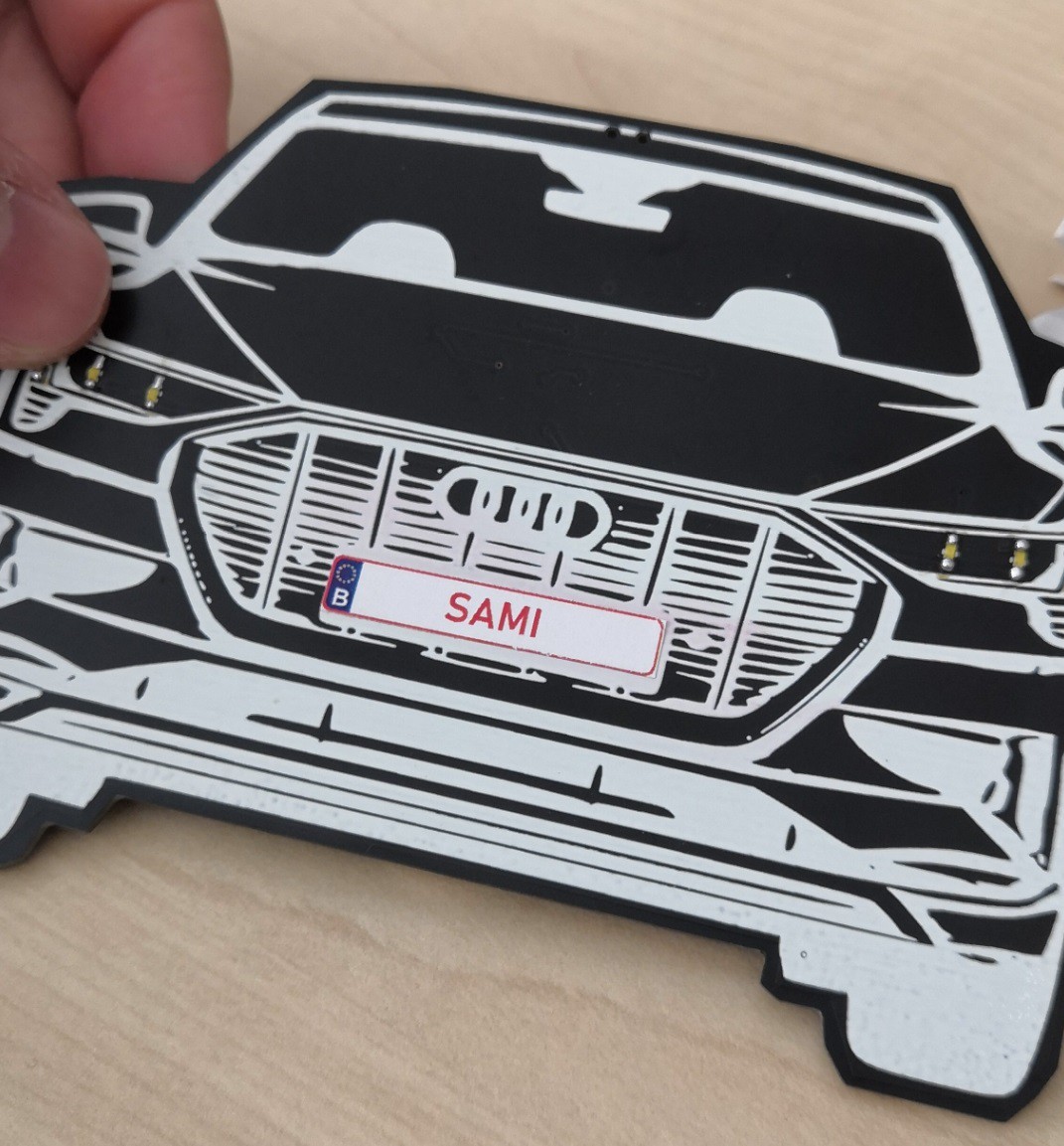
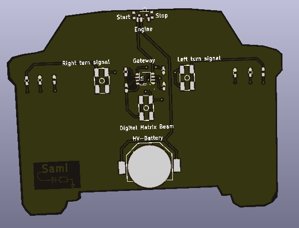
SamiThis decorative PCB on a wooden lasercut stand was a gift for my colleagues that left for another location.
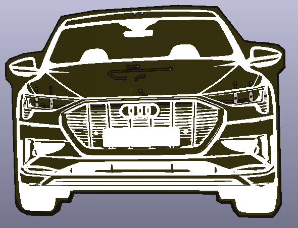
I took care to have Easter eggs on the product we're working on - the Audi e-tron - to let them not forget the months we worked and struggled together on that project.
I've also let a blank spot on the number plate to stick a personalized Belgian plate with their name on it.
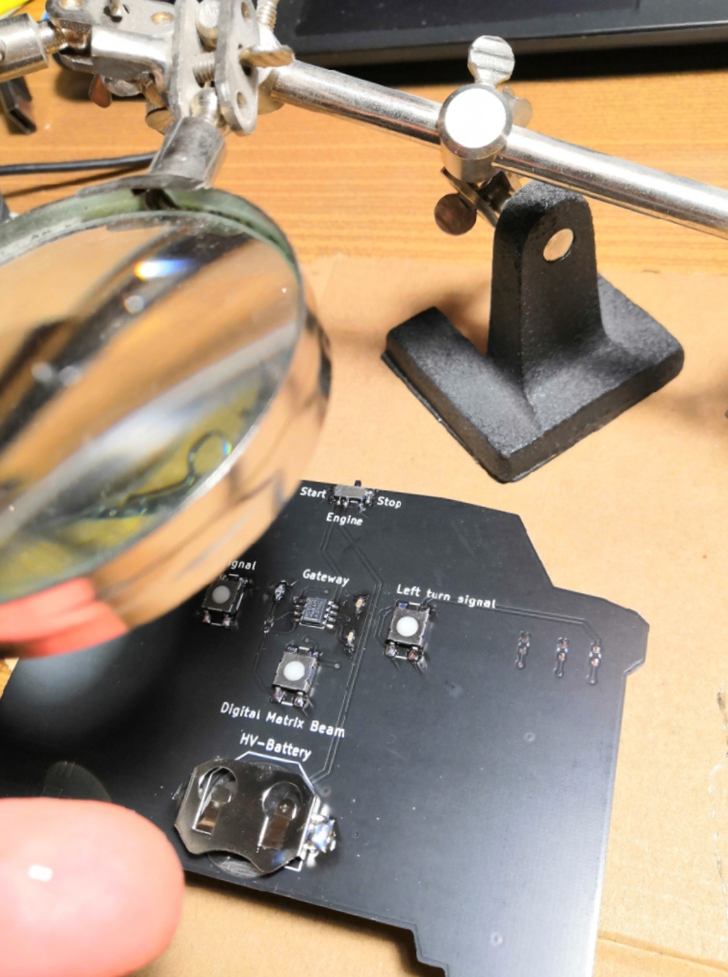
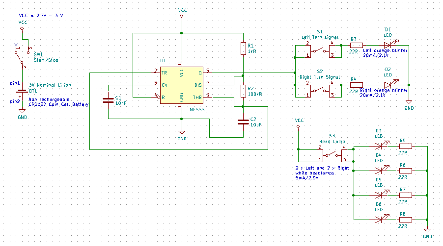
You'll find the design considerations and limitations I had in the instructions.

 setCREATE
 Alpenglow Industries
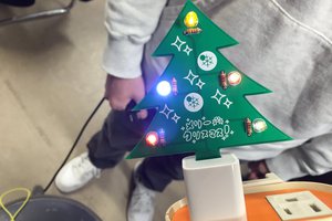
 Elecrow