Close
0%
0%

ATTiny555

What, you're using a 555? I could've done that with a microcontroller!

Similar projects worth following
The ATTiny555 is a 555 timer being simulated on an ATTiny85. If you can do a microcontroller project with a 555, why can't I do a 555 project with a microcontroller?

This abomination of analog and digital circuitry reared its ugly head because I was too lazy to order a 555 off of Amazon. I already had a few ATTiny85s laying around, so why not? Two-day shipping is apparently too slow, so now I'm going to make my own.

After six hours of reading the ATTiny85 datasheets and refamiliarizing myself with my past demons, I present to you: the ATTiny555.

It features:
- A lower operating voltage range (1.8-6.0V)
- The same pinout as a 555
- A lackluster analog bandwidth
- And questionable power consumption characteristics!

It's definitely a lot better than those weird, gross 555 timers everyone's talking about. Blech.

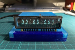
Woah, check it out, it's a video of a prototype ATTiny555 working! You should totally watch it!

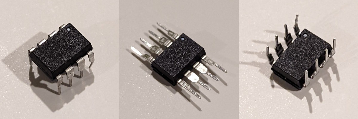
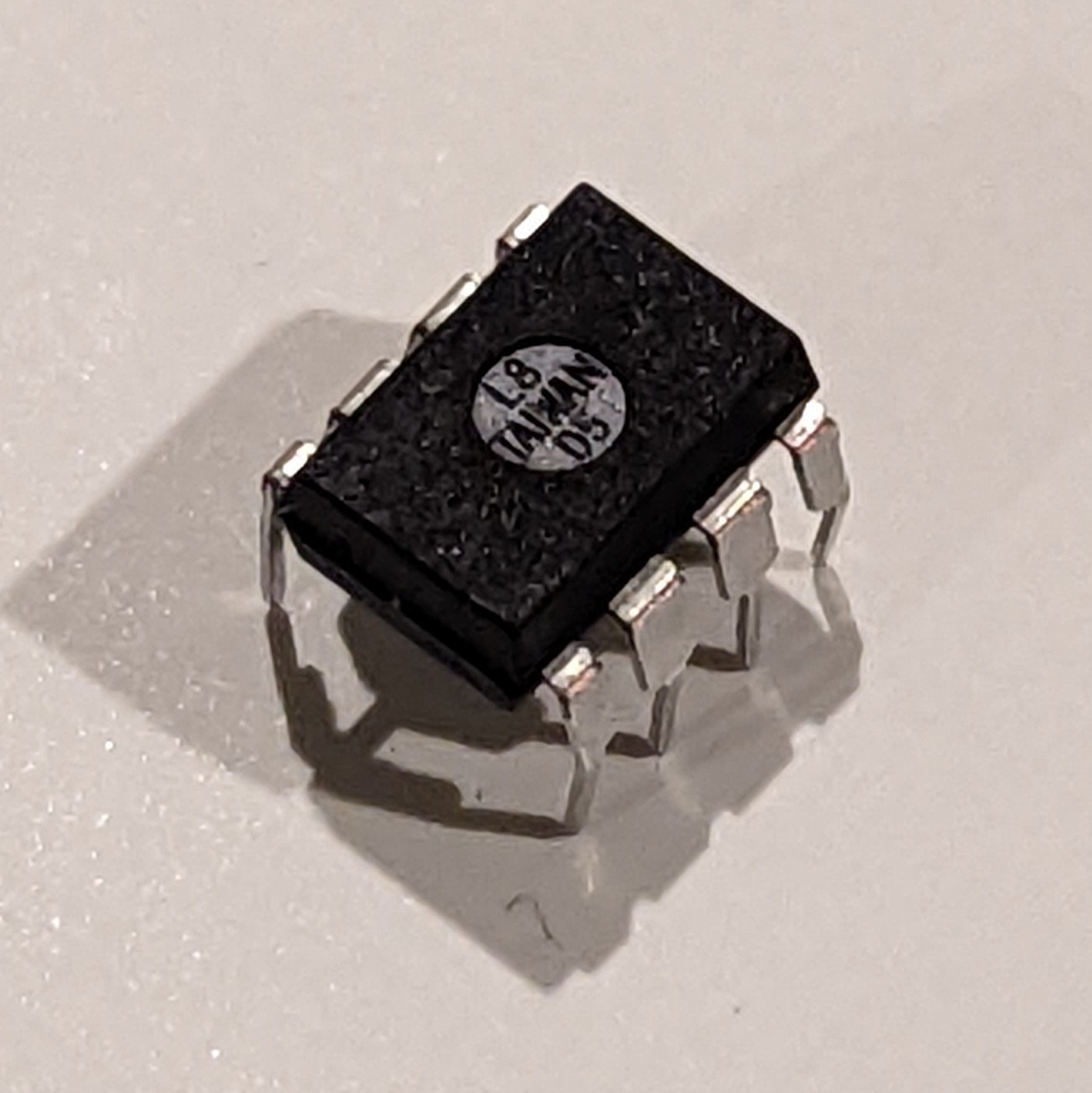
This animation isn't programmed-- It's a visual indicator of the 555 circuit running in real time! I coded my own custom output pin functionality so that the ATTiny555 drives Neopixels instead of outputting a binary signal.

Read more »

  • 1 × ATTiny85 The brains of the whole operation. There's a fair chance you could use an ATTiny25 (or even an ATTiny15), but I haven't tested it with those personally.
  • 1 × 68KOhm Resistor Only use this if you're planning on building the original version.

  • Can your 555 do this?

    Shranav Palakurthi01/07/2022 at 03:43 0 comments

    By overriding the output pin, I was able to get the ATTiny555 display its internal state on a Neopixel ring. Pretty cool, right?

    You can check out the source code here!

  • Making the ATTiny555 more than a 1-trick pony

    Shranav Palakurthi01/06/2022 at 22:04 0 comments

    @prabbit237 suggested an alternative way to set up the ATTiny555 so that it can be used for rapid prototyping, and I've used it to update the whole system and simplify the build process. 

    I'm soldering pin headers on the back of the chip, like so:

    so I can reprogram the chip as many times as I like!

    Now, all the 555-related code is in a single header, making it easy to integrate into whatever project you like. It just needs 2 extra lines of code:

    #include "ATTiny555.h"
    
    void setup() {
      AT555_begin();
    }
    
    void loop() {
      // your stuff here!
    }

    And because it uses interrupts, it leaves the loop completely open for you to do whatever you want!

    What I find cool about this is that people have actually found potential use cases for this project (Looking at you, @Matthias Urlichs), so I think it's good that all the code is simpler to use.

  • Chip Flip Success

    Shranav Palakurthi12/16/2021 at 03:42 0 comments

    I finally got the time to code the ATTiny555 so that it works using a flipped and rotated chip, making it a near-perfect pin-compatible drop in for the real 555. 

    With this change, I was able to trade The Gotcha (the ground and reset pins being switched) for a smaller, almost unnoticeable catch (the control pin being connected to VCC). In most 555 timer circuits, the control pin is isolated to ground via a filtering capacitor, meaning that it could be at any reasonable voltage without causing problems. However, for the situations where you might need the control pin, take a long look in a mirror and ask yourself why you're entertaining the idea of using a microcontroller to genuinely replace an existing 555 timer. 

    For my sanity, and yours.

    Anyways, this new version is now 100% pin compatible with a 555, and depending on the application, a drop-in replacement for the real stuff!

    Here's an ATTiny85 running the new code, pre-operation.

    With the code verified, it was time to make it a real 555! Hand me my scalpel, I'm going in.

    To do this, I had to bend the chip's pins backwards...

    Doing some stretching exercises with the lil' ATTiny

    Unfortunately, this caused some cracking near the pin's bases, which I tried to solve by filling them with solder.

    Take a close look at the copper-colored stripes near the pin bases

    With limited success, unfortunately.

    Here's how it looked like after. It was hard to get the solder in the cracks.

    Ignoring that mechanical flaw, I bridged what used to be PB0 with the VCC pin using a cut resistor lead I had laying around.

    The ATTiny555 with the bridge wire between PB0 and VCC.

    And there it is! An ATTiny555 in all of its (limited) glory. No external components required!

  • A Crime Towards Chip Design

    Shranav Palakurthi12/11/2021 at 01:30 0 comments

    ...or a win for hackers?

    I'm not sure.

    In my pursuit of complete pin-compatibility, I think I found the solution. And guess what? It doesn't need any external components (more on that later).

    A pinout of the 555 (left) compared the the ATTiny85 (right)

    As it is right now, the ATTiny555 is placed in a "standard" orientation, which means that the top of the chip is at the top of where the 555 would have been.

    Although everything works as expected, there's still the issue of the ground and reset pins being swapped. Since both of these pins are connected in hardware, there isn't much that we can do about changing it. Although you can reflash the chip to disable the reset, it doesn't do much to help with the pinout issue.

    But, what if the chip was flipped and rotated 180 degrees?

    Now, the ground and reset pins are aligned.

    But what about VCC? It's now where the control pin is. Well, here's the good news: normally, the control pin is isolated from ground via a capacitor. That helps us. All we have to do is bridge PB0 (the top right pin on the flipped/rotated chip) to the VCC pin, and we should be good. Since both the trigger and threshold pins are now aligned with ADC inputs, there's no need for external components! Cool!

    I'm going to try this and let you all know how it goes.

View all 4 project logs

  • 1
    Flash the firmware

    Download (or clone) the GitHub repository to a folder on your computer.

    If you are building the original version, make sure to uncomment the following line at the top of ATTiny555.ino:

    //#define AT555_ORIGINAL // comment out to use the original layout

    Compile and upload the code to ATTiny85 using whatever programmer you like. For me, I used an UNO as an ISP

    Because code is in a .ino file, you need the Arduino IDE.

  • 2
    (Original version) Solder the backpack on

    If you're building the original version of the project, take the 68KOhm resistor, shorten its leads, and use it to bridge the bottom two pins of the ATTiny85 (PB0 and GND), like so:

    Make sure that the resistor bridges the two pins on opposite sides of the IC that are furthest from its orientation dot.

  • 3
    (Flip-chip version) Flip the chip

    If you're building the flip-chip version of the project, take the chip and bend its leads backwards carefully. From my experience, they are prone to cracking at the base and breaking. I bent them against a flat surface, like a table edge.

    Once the leads are bent backwards, use a wire to bridge pins PB0 and VCC. 

    You should end up with something like this:

    That's it!

View all 4 instructions

Enjoy this project?

Share

Discussions

Mingjie Li wrote 07/28/2023 at 10:40 point

What about a CH32V003J4M6 version? Even cheaper.

  Are you sure? yes | no

nrwest wrote 12/22/2021 at 20:44 point

This is gold! Nice work. In a lot of ways the ATTiny85 is already a natural successor to the 555 - cheap, rugged, versatile... but your trick is really clever.

  Are you sure? yes | no

Shranav Palakurthi wrote 12/24/2021 at 01:15 point

Thanks :D

  Are you sure? yes | no

prabbit237 wrote 12/21/2021 at 12:49 point

Instead of bending the leads backwards, you could just solder on 2 sets of 4 male header pins so that they point back the other way. If you wanted it to be a bit neater, you could clip the narrower sections of the original pins or you could just leave them sticking out.

  Are you sure? yes | no

Shranav Palakurthi wrote 12/21/2021 at 18:49 point

That's a good idea! I'm going to try that later today.

  Are you sure? yes | no

prabbit237 wrote 12/21/2021 at 21:10 point

I wasn't thinking about this at the time but flipping a chip could also be a good way to rework the wiring on a circuit board on occasion. It could mean not having crossing traces or jumper wires at times. 

  Are you sure? yes | no

Similar Projects

Does this project spark your interest?

Become a member to follow this project and never miss any updates