 Shranav Palakurthi
Woah, check it out, it's a video of a prototype ATTiny555 working! You should totally watch it!
This animation isn't programmed-- It's a visual indicator of the 555 circuit running in real time! I coded my own custom output pin functionality so that the ATTiny555 drives Neopixels instead of outputting a binary signal.
The Rules of the Game
To my understanding, the 555 timer works based on these simple rules:
- When the voltage on THRES rises above two-thirds of the input voltage, the OUT pin is pulled low and the DIS pin is set to sink current.
- When the voltage on TRIG drops below one-third of the input voltage, the OUT pin is pulled high and the DIS pin is set to high impedance (essentially making it float)
- When RESET is pulled low, OUT is pulled low and the DIS pin is set to high impedance.
I have two versions of the ATTiny555, each with its own quirks and tradeoffs. To summarize, here's a chart:
| Original | Flip-Chip | |
|---|---|---|
| CTRL Pin Voltage | 2/3 VCC | VCC |
| Is it a pin-compatible 555 replacement? | Nah | Yeah!* |
| Is it an abomination? | Yes. | Yes. |
*sorta.
Let's take a closer look at the two versions of the chips. Here's their pinouts, compared to a 555.
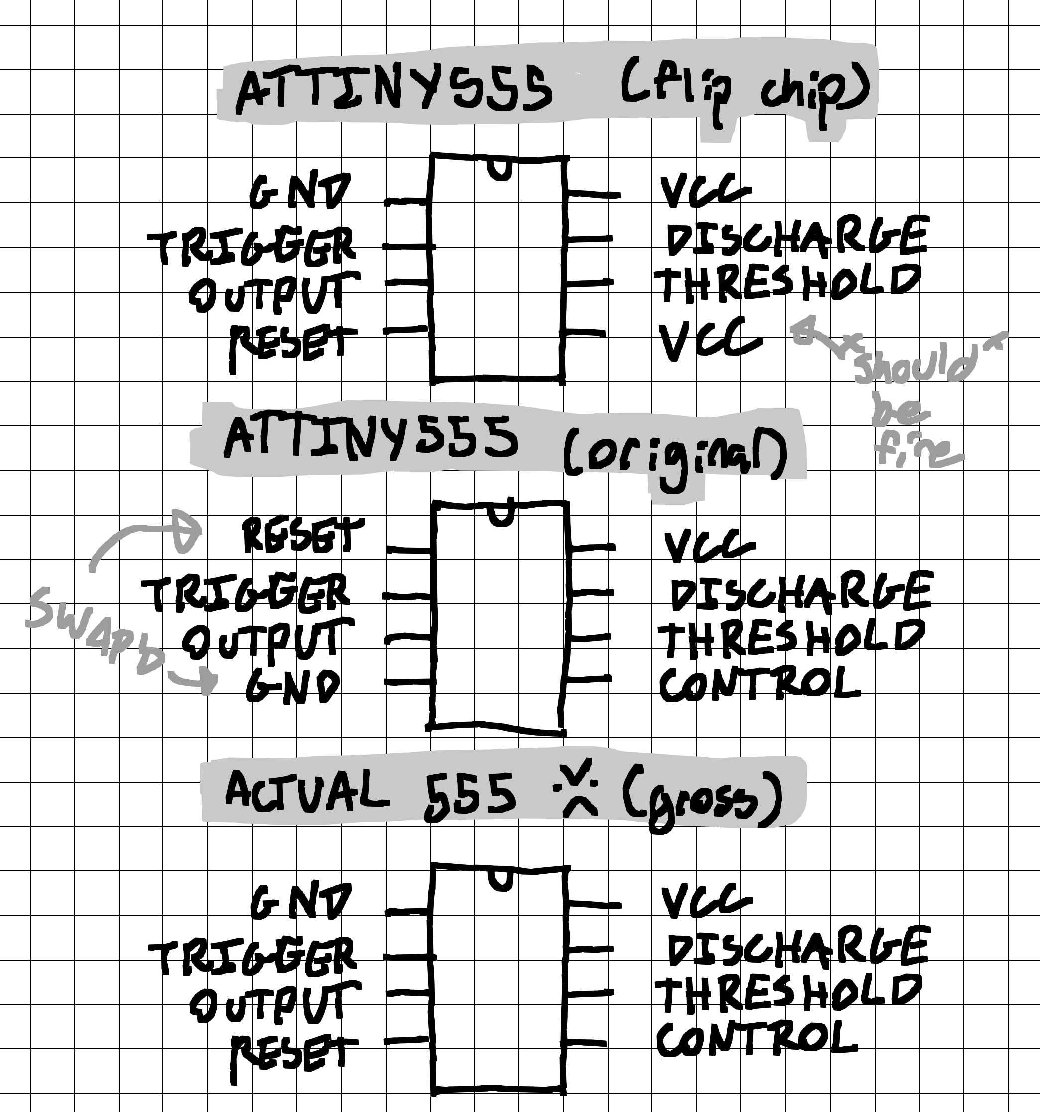
Note how the GND and reset pins are switched in the original version of the chip... This can be tricky when you try to use it as a drop-in replacement for a 555, because during normal operation, the 555's reset pin should be connected connected to VCC, which would brown-out the ATTiny555 because the voltage between VCC and GND would be 0V. Not good.
Also keep in mind that what would be the control pin on the 555 is actually connected to VCC pin on the flip-chip version. Most of the time, the control pin is isolated from GND using a filter capacitor, so it should be fine... Just don't expect to get any analog references from the flip-chip version, it's all digital inside.
In short,
- If you need the CTRL pin (and marginally better analog bandwidth), use the original version!
- If you need pin-compatibility, use the flip-chip version!
The Guts
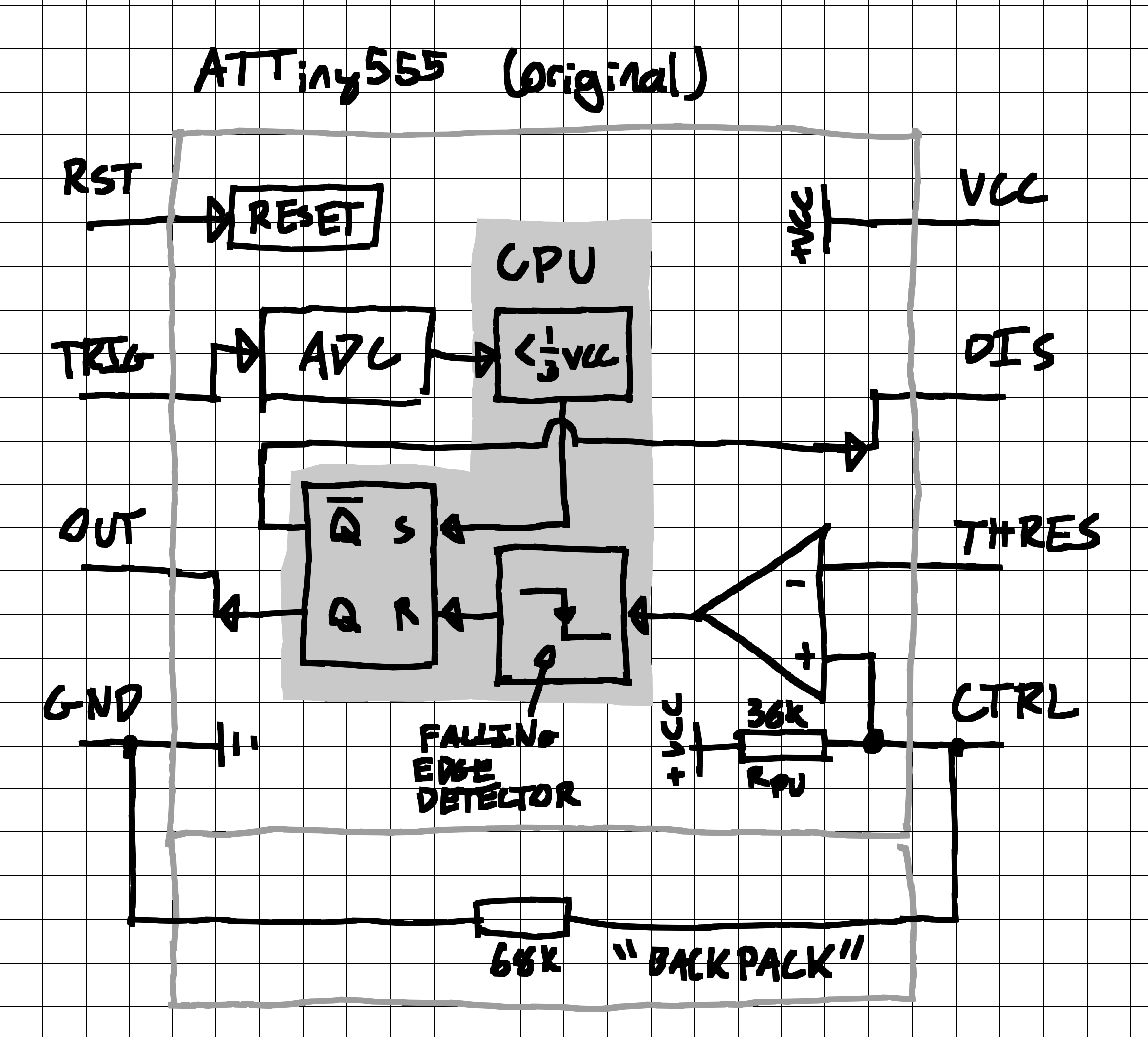
Beyond those caveats, however, both are a 1:1 simulation of a 555 timer based on the rules above. On the inside, the original looks like this:
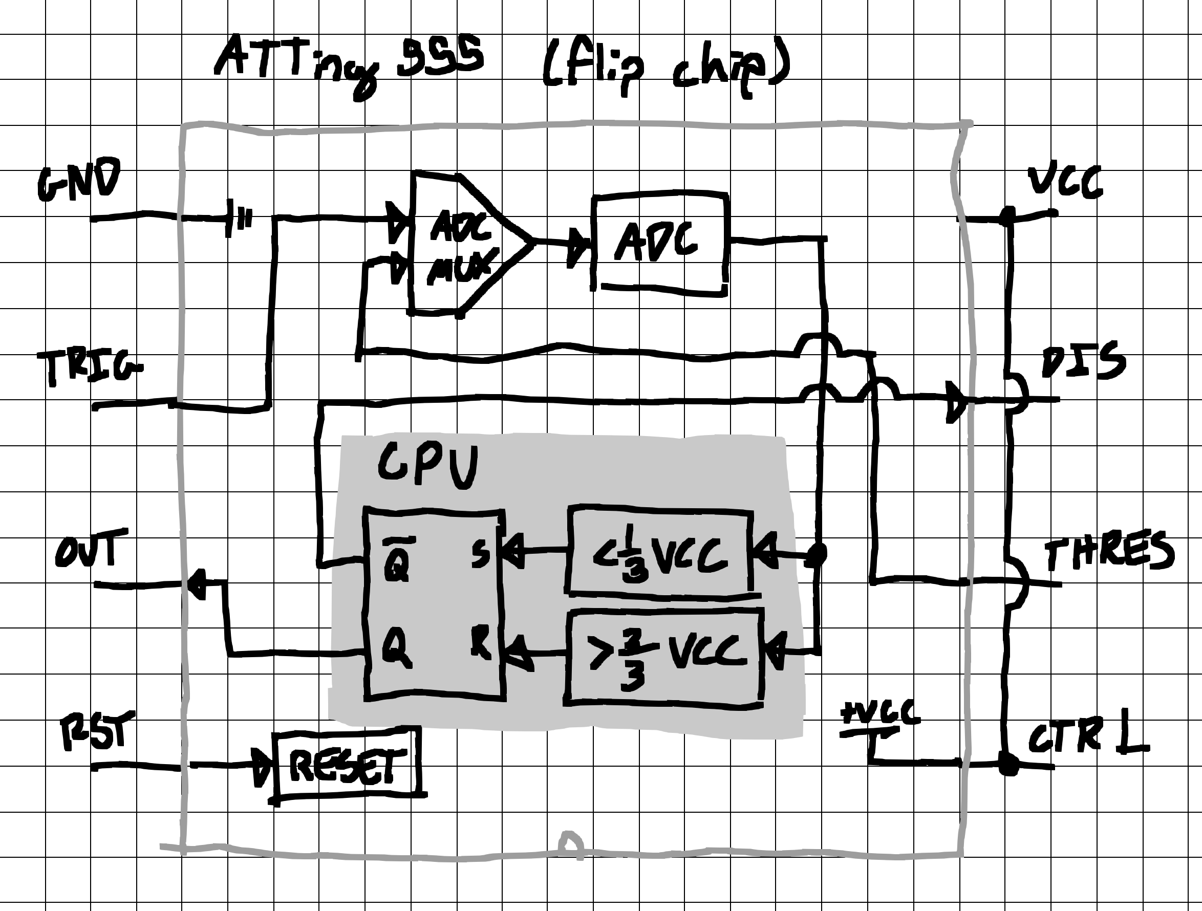
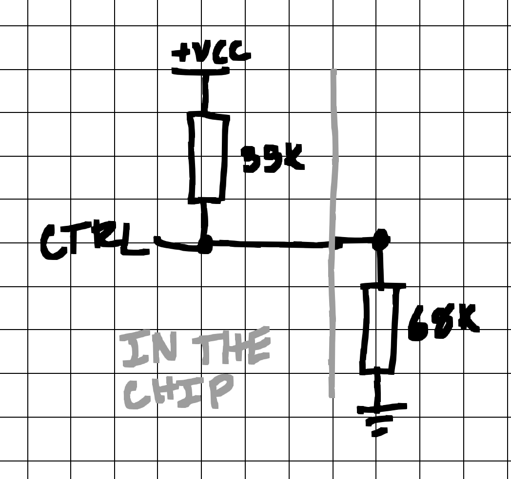
And the flip-chip version looks like this:
I know they both look a little busy, so let's break it down!
In both versions, there are two main voltage monitoring systems. Since the system is interrupt-based, the Arduino main loop is entirely empty, and can be used for user code. Take that as you will. (multiprocessing 555?)
Control Loop 1: Threshold Pin
The first loop is the threshold monitoring loop. It functions differently based on which version of the chip you're planning on using, so read carefully!
In the original chip, the monitoring loop makes use of the ATTiny's analog comparator and some clever tricks with the input pull-up resistors. Essentially, both the threshold pin and control pin are set up as inputs to the ATTiny's analog comparator. But this poses a problem. How can you generate a voltage that is two-thirds of VCC with a minimal number of external components? Well, as it turns out, an external voltage divider is pretty darn easy to implement, which is what I initially did.
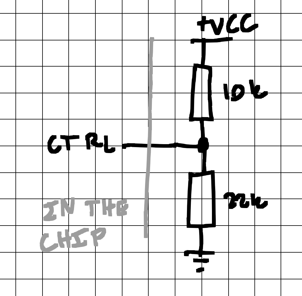
But wait-- the datasheet mentions that each digital I/O pin has an internal pull-up resistor! What if I used it as the high side of the voltage divider on the control pin?
The datasheet has something to say about that:
[when using a pin as an input to the analog comparator] configure the port pin as input with the internal pull-up switched off to avoid the digital port function from interfering with the function of the Analog Comparator.
Mmmmmm-- I'm gonna pretend I didn't read that. I'm still going to use the internal pull-ups as the high side of the voltage divider. I mean, this type interference might actually be a good thing because it's the type of interference I want!
But how do you know what resistance to use on the low side of the voltage divider when you don't know what the pull-up resistance is? The datasheet isn't particularly helpful on this front:
| Parameter | Min. | Typ. | Max. |
|---|---|---|---|
| I/O Pin Pull-up Resistor | 20 KOhms | 50 KOhms |
No typical value? Seriously?
Of course, you could guesstimate the resistance to be exactly in between the maximum and minimum, 35 KOhms, but what if it wasn't? Surely the engineers made the tolerances so lax for a reason... Well, once I cracked out my multimeter and actually measured it, I was surprised to see that it was exactly where it should be: 35 KOhms. Good job, Atme--err Microchip.
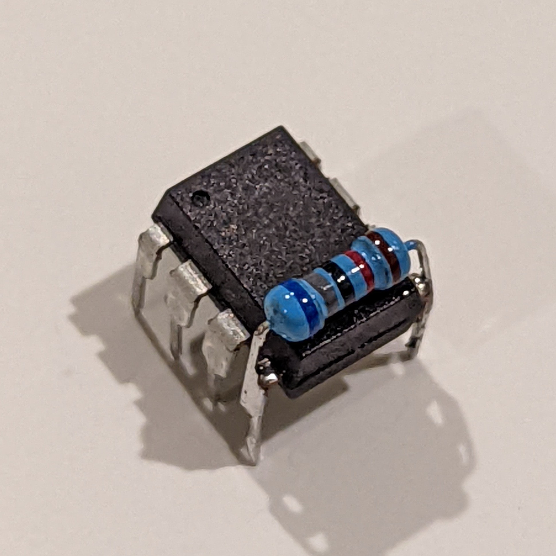
Based on that, the low side resistor should be 70 KOhms. But I didn't have a 70 KOhm resistor, so I just used the next best thing: a 68 KOhm resistor. All that was left to do was solder the 68 KOhm resistor to bridge the control and ground pins, essentially creating an equivalent voltage divider with one less external component. Nice!
I have lovingly named the tacked-on resistor "The Backpack".
Because the comparator outputs high when the threshold pin's voltage is lower than two-thirds of the input voltage, we need to see when the comparator's output drops to low, because that's when the threshold pin's voltage is higher than two-thirds of the input voltage. Every time that happens, the output is set to low and the discharge pin is connected to ground.
In the flip-chip version, the chip simply monitors the threshold pin by continually sampling it using the ADC. When it's above two-thirds of the input voltage, the output is set to low and the discharge pin is connected to ground.
Control Loop 2: Trigger Pin
The second loop is the trigger monitoring loop, which utilizes the ATTiny's onboard ADC to continuously sample the voltage on the trigger pin. If the ADC readout is less than one-third of the input voltage, then the output is set to high and the discharge is set to high-impedance.
Control Loop 3: Resetting
Well, this is built into the IC, so there's not much to explain here. When the reset pin is pulled low, the chip resets. Simple as that.
Putting it all together
These three control loops form the basis of the 555 timer, both of which are simulated on the ATTiny555 in some way. I've used the ATTiny555 in place of an actual 555 and it works exactly as intended, so take that, hardcore electrical engineers! I think I won...
If it wasn't clear already, this project is a joke. I hope you found it funny, because I sure did.
Happy hacking!