Close
0%
0%

555 MPP solar charger

A very simple, low cost MPP solar charger built around the venerable 555 timer

Similar projects worth following
The 555 Timer Contest got the creative juices flowing, but looking at the rules page, it's obvious that "creative" is pretty much assumed to be "artsy". The engineer in me wanted to show that it's possible to be "creative" in coming up with unusual but useful applications for common chips as well, it doesn't always need to involve blinking LEDs and making sounds! So, doing what I do with power circuitry, batteries and solar, here's a 555 based MPP solar charger!

Some design goals:

  • Use a 555 central to the design, with minimal additional circuitry.
  • Keep it simple.  A real-life implementation should add under voltage lockout for the load and over and under-temperature lockout for charging, but adding these would obscure the simplicity of the basic charging circuit.
  • My design is for LiFePO4 batteries (3.6V max) but with some resistor changes it can be altered for LiPo (4.2V max, but not recommended as charge current is not regulated) or Lithium Titanate (LTO 2.8V max).

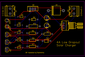
An LTSpice simulation circuit is shown below:

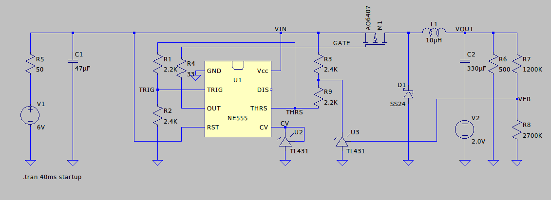
Notes about the schematic:

  • V1 and R5 simulate a "weak" power source with high internal resistance, such as a solar panel.
  • C2 and V2 are a model for a very low capacity battery, starting at 2V.
  • R6 represents a load.
  • The rest of the circuitry is the actual charger circuitry.
  • This doesn't do Maximum Power Point Tracking (MPPT) but simple MPP with a pre-set voltage, which means the charger will not allow the input voltage to fall below a certain level, this voltage should be configured to the MPP voltage of the solar panel.
  • There is no charge current limiter, limit the charge current by using a small enough solar panel that doesn't have the power to provide a current too high for the battery. :)
  • The 555 is used as a comparator with hysteresis that drives the power MOSFET M1 which, together with D1, L1, and an output cap (combined here with "battery" C2) makes up a buck converter.
  • Since the solar panel MPP voltage and the battery "full" voltage require absolute voltage levels, and the 555 is ratiometric and knows nothing about absolute voltages, we add two references U2 (for MPP level, biased through the 555's internal 5K resistive divider) and U3 (for battery full level, biased through R3) to be able to detect these voltages.

Below is a simulation trace:

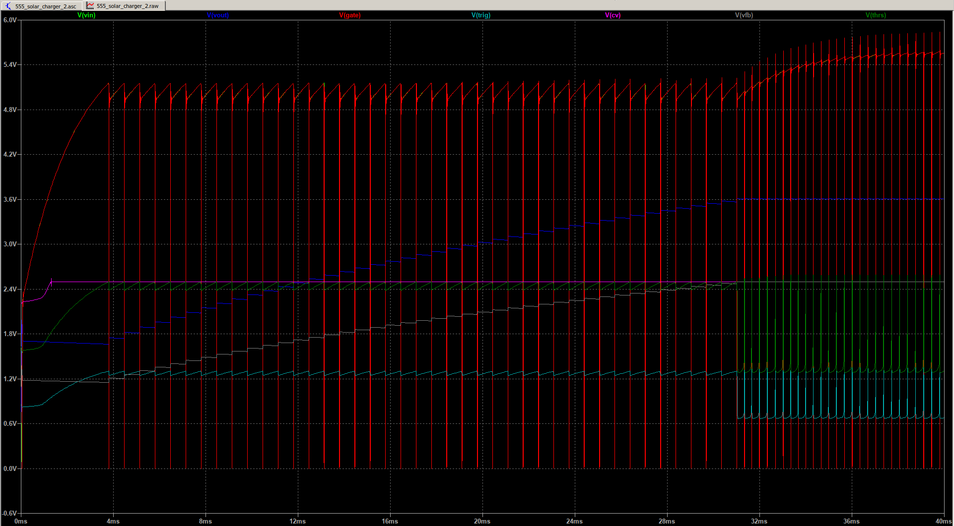
At the very beginning of the trace, the input cap C1 is charging, and the circuit is not switching because the input voltage is below the MPP voltage, which in this circuit is set to ~5V.  Once 5V is reached, the switcher built around the 555 starts.  There is no timing cap in the circuit, the timing is derived from the input voltage going above MPP level (THRS rises above CV) and falling below the MPP level (TRIG goes below CV/2).  The hysteresis is created by R1 and R2 having slightly different values.  The actual switching frequency is dependent on incoming power, input cap size, output cap size and load).

As you can see in the trace, from 4 to ~30 ms, the input voltage stays around the MPP level of 5V, and the output voltage (the blue trace) goes up as the "battery" charges.

When the output voltage reaches 3.6V (battery full level for LiFePO4), the voltage VFB generated by divider R7/R8 reaches 2.5V, which makes reference U3 conduct.  This pulls THRS low, preventing its voltage level from going above CV and this prevents M1 from being turned on, effectively causing charge termination.

So why do we still see switching after ~30 ms?  Because load R6 is discharging the battery, so the voltage drops below 3.6V which re-enables the switcher.  As you can see, the input voltage is not held at around 5V anymore but is allowed to go higher, switching just happens as needed to keep the voltage stable at 3.6V.

In the trace below, we have increased the load by a factor 1000x to 500K:

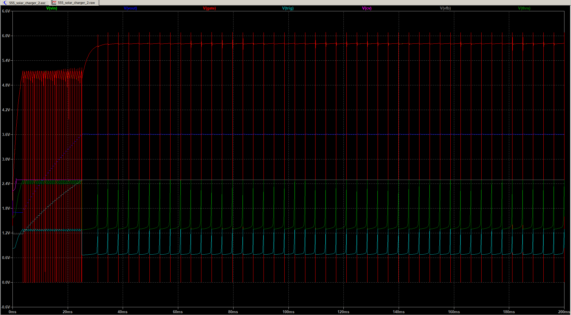
Because it is not being discharged while also charging, the small battery reaches the "full" level of 3.6V much quicker, and because the load is low, there are much less switching cycles when the battery is full because it is being discharged much slower.

If using a LiFePO4 cell, the battery voltage can be used to power 3.3V circuitry directly, IF the circuitry goes into a low power mode when the voltage falls below 2.9V or so to prevent the battery from over discharging.

If a different "full" voltage for the battery is desired, divider R7/R8 can be adjusted accordingly.

R3 can be adjusted to set a different MPP voltage...

Read more »

555_solar_charger_3.asc

555 based MPP solar charger LTSpice schematic, with over discharge and under temperature protection and battery heater

plain - 4.77 kB - 01/07/2022 at 20:02

Download

AZ432.asy

AZ432 symbol used in the schematic

x-wine-extension-asy - 627.00 bytes - 01/07/2022 at 20:01

Download

az432.mod

Model for AZ432 used in the schematic

x-mod - 291.00 bytes - 01/07/2022 at 20:00

Download

tl431.mod

Model for TL431 used in the schematic

x-mod - 292.00 bytes - 12/10/2021 at 22:57

Download

TL431.asy

TL431 symbol used in the schematic

x-wine-extension-asy - 626.00 bytes - 12/10/2021 at 22:57

Download

View all 6 files

  • PCBA ordered from JLCPCB

    Patrick Van Oosterwijck01/09/2022 at 22:10 0 comments

    I went ahead and ordered PCBs and assembly from JLCPCB.  There was a little more friction to the process than I had hoped.

    The service is picky about the formats for the BOM and placement files, and it seems some parts that looked available on LCSC were actually not available for the assembly service, so I had to select other ones.  I would recommend that if you intend to use this, you start from the "Basic" parts library.  Because I didn't, I also had a good number of special parts that added cost to my order.  Oh well, lesson learned.

    Unfortunately the position data for assembly exported from KiCad also couldn't be directly ingested by JLCPCB, it took some manual massaging in a spreadsheet to get it right.

    But in the end, getting 5 prototype PCBs produced, fully SMT assembled and shipped for about $72 is still a very good deal!

  • KiCad prototype design

    Patrick Van Oosterwijck01/07/2022 at 19:46 0 comments

    Well, I couldn't help myself I guess. 🙂

    KiCad 6 had just been released, I was on vacation and sometimes needed to fill some idle time, so I decided this was a nice small project to get some more KiCad experience.  Who knows, maybe if it works well, it might become a product too.

    To make the LTSpice concept more practically useful, a couple of things needed to be added:

    • Over discharge protection
    • Preventing the battery from back feeding the 555 charger
    • Under temperature protection
    • A battery heater to get the battery up to temperature for charging

    These needed to be added with minimal circuitry and cost to stay true to the concept that this is a 555 based circuit first and foremost.

    A couple of limitations remain:

    • Maximum input voltage is 16V due to the 555 input voltage limit.  This is just fine, but something to keep in mind when choosing a solar panel.  I switched to the SA555 to get wide temperature range for outdoor use.
    • The input source needs to be a "weak" source like a solar panel.  Since the switching depends on the input voltage drooping when loaded, a strong source that doesn't droop would probably burn something up.  So this shouldn't be used with large powerful solar panels or wall power.
    • No charge current limiting.  Keep the solar panel small enough to limit the current to 1A or so.
    • No over temperature protection.

    I implemented it with these features:

    • A board stuck to the back of an 18650 battery holder that will hold a LiFePO4.
    • Screw terminals for VIN (solar panel) and VOUT (load switch protected battery voltage).
    • A pot for adjusting the MPP voltage to what's ideal for the panel.
    • NTC thermistor and two heating resistors on the PCB.  Battery heating also adjusts to the same MPP voltage as charging does!

    I'm quite happy with how such a basic and cheap circuit can do all this.

    Here's the beautiful 3D view generated by KiCad:

    The pretty logos were probably not necessary for a prototype that may never make it to production, but I felt it was an important part of the learning experience to see how well KiCad handles these things.  And to be honest, I was a bit disappointed.  There is a function to import SVGs but when I tried it, I would just get white boxes.  I had to resort to using this Inkscape plugin to make it work.

    Next, I think I'm going to try JLCPCB's assembly service to get some prototypes and see how that works.  This should be a good test since all the parts are on LCSC anyway.

  • Have fun with it!

    Patrick Van Oosterwijck12/10/2021 at 23:08 0 comments

    This was a fun circuit to design, and it's not entirely frivolous!

    In these times of chip shortages, it can be very useful to base a design on bog standard generic parts that are produced by many manufacturers, such as the 555 and TL431 used in this design, versus doing a design requiring specific components that may only be available from a single source.

    You can download the file and play with it in LTSpice, it's a fun way to learn about simulation, and it can give you a nice feel for how the circuit works.  Try to change the input voltage V1 or source resistance R5 and see how it affects operation.  Or vary the load and see what happens.  Or change R3 and see how it affects the MPP voltage.

    I don't really have any plans to turn this into actual hardware, but it's tempting just to see how well it works in reality.  I guess I may do it if there's enough interest!

View all 3 project logs

Enjoy this project?

Share

Discussions

SnowW wrote 12/12/2021 at 06:53 point

I think it is a useful and creative design. As you said, for some things, generic components can be very useful, especially when specialized components are hard to get. Thanks!

  Are you sure? yes | no

Similar Projects

Does this project spark your interest?

Become a member to follow this project and never miss any updates