 Adrian Studer
Addressable RGB LEDs are driven through a series of pulses, with different pulse-widths representing 1s and 0s making up 24 bit colors, and another longer pulse to mark the end of a refresh cycle. Sounds like the perfect target to exercise a handful of 555 timers.
The project can be split into two parts:
- Driver for the LED strip
- Generator of the color patterns
RGB LED DRIVER
The protocol to talk to RGB LEDs consists of three pulses. According the datasheet for the common WS2812B those are:
- 0 bit: 0.4 us high and 0.85 us low
- 1 bit: 0.8 us high and 0.45 us low
- reset: longer than 50 us low
The datasheet specifies +/- 150 ns, but luckily for us the LEDs are not that fussy.
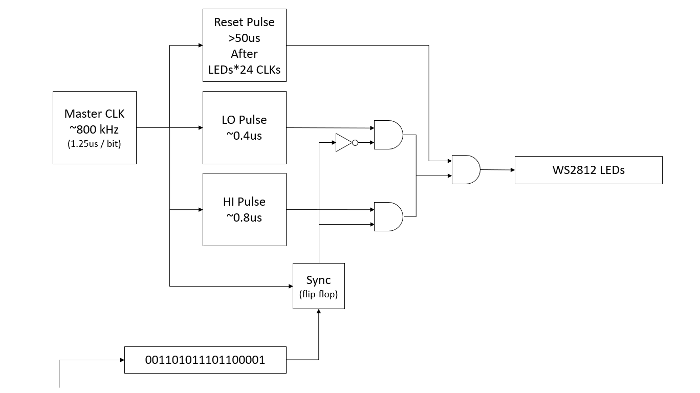
The plan is to use a 555 configured as an astable oscillator to generate the master clock at approximately 800 kHz, which is equal to the duration of one bit.
Two monostable oscillators generate the 0.4 us pulse for 0 bits and 0.8 us for 1 bits respectively. Two AND gates and a NOT gate select one of the two pulses depending on whether a 0 or 1 bit needs to be sent to the LEDs. The flip-flop synchronizes the incoming bit stream (more on that later) with the master clock to avoid switching in the middle of a bit.
For the reset pulse, a counter and a bunch of logic gates will count the bits and trigger another monostable oscillator after all LEDs are updated. The output signal of this module is normally high and goes low for 50 us, overriding any other output via the AND gate.
PATTERN GENERATOR
Now we need some interesting bits to send to the LEDs.
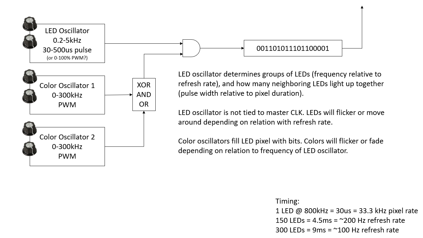
The basic idea is to have three oscillators that create waves of 1s and 0s, with the hope that harmonics between the different frequencies and the length of the LED strip results in interesting patterns.
Sticking with the 555 theme, we will borrow the Atari Punk Console circuit for the oscillators. The frequency and pulse pattern of each oscillator is tuned by twiddling two knobs. The color oscillators will be mixed by some tbd and/or configurable logic.
Bits coming out of the first oscillator are at a lower frequency and will determine which LEDs are on. The other two oscillators run at higher frequencies to fill in the bits, i.e. colors of the enabled LEDs.
Hard to predict if this contraption will result in something pretty. We may have to replace this with an oscillator per RGB channel and a multiplexer driven by the master clock.
CIRCUITS
At the core of the RGB LED driver circuit are four 555 timers, split across two Texas Instruments TLC556. Note that the datasheet of this part specifies a maximum frequency of 1-2 MHz. Many variations of the 555 timer only support up to a few 100 kHz which would be too slow for our purpose.
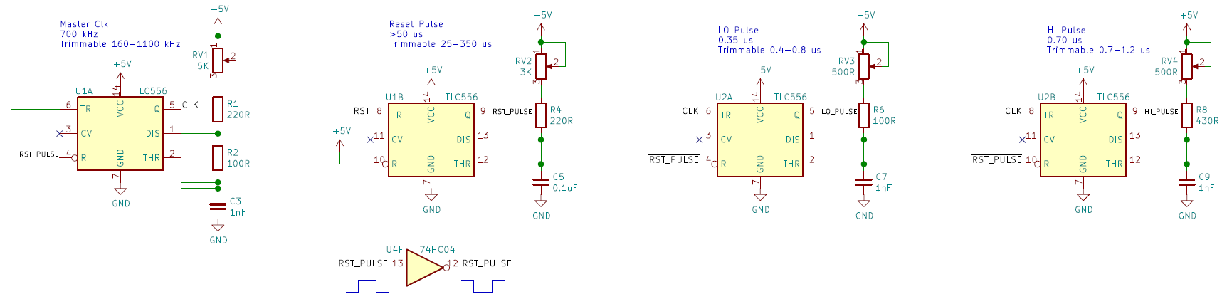
The first 555 is configured as astable oscillator generating the CLK signal, trimmed to approximately 700 kHz. A small value is picked for R2 to make the negative part of the clock waveform as short as possible.
CLK is the trigger for the monostable oscillators that generate the LO (0-bit) and HI (1-bit) pulses. Each time CLK goes to 0, LO and HI will output 1 on their output (LO_PULSE and HI_PULSE) for the time set by their resistors. Both oscillators are trimmed to the lower end of their range to meet the requirements of the RGB LED.
Another 555 is setup to ouput 50 us reset pulses (turns out we needed >280us, see update). This monostable oscillator is triggered when RST goes low. A NOT gate converts the positive going RST_PULSE into a negative ~RST_PULSE, which is used to reset and temporarily pause the other timers during reset.
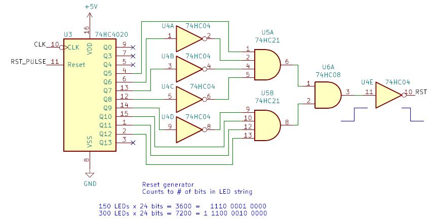
74HC4020 is a counter that increments for each (negative) pulse of the CLK signal. With 8 data bits per color per LED, we need to count LED x 24 bits before triggering the reset pulse. NOT and AND gates are used to create a signal that goes high when reaching 7200 for a string of 300 LEDs. The final NOT gate inverts the signal as we need a negative RST pulse to trigger the reset timer. The output of the reset timer (RST_PULSE) is also used to set the counter back to 0.
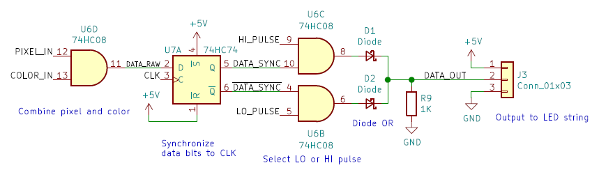
The color mixer circuit selects between HI_PULSE and LO_PULSE based on whether a 1-bit or 0-bit needs to be sent to the RGB LED. The AND gate U6D will go high if both PIXEL_IN (is the pixel on?) and COLOR_IN (color bit) are high and stays low otherwise.
This signal is then fed into a flip-flop that is running on the same CLK signal as the HI and LO pulse generators. The output of the flip-flop will only change on the falling edge of CLK, synchronizing is with the pulse generators.
When the data bit is a 1, DATA_SYNC will be high and U6C will go high for the duration of the HI_PULSE. When the data bit is 0, ~DATASYNC will be high and U6B will go high for the duration of the LO_PULSE.
Two diodes and a pull-down resistor form an OR gate that combines the output of U6B and U6C. We could have used a 74HC32, but that seemed overkill as we only need one gate.
You may wonder why the ~RST_PULSE signal does not show up in this sub-circuit. That's because ~RST_PULSE will pause HI_PULSE and LO_PULSE, i.e. they will always be low for the duration of the reset pulse, and therefore DATA_OUT will be 0 as required by the RGB LED.
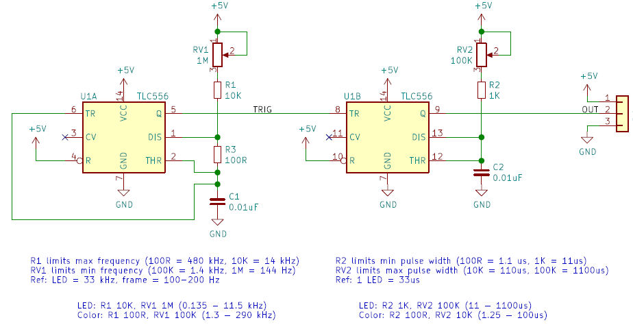
The circuit for creating the bit stream was borrowed from the famous Atari Punk Console. A few resistors were added or shuffled around, but it still functions the same way with potentiometer RV1 controlling the frequency and RV2 the pulse-width.
The NeoPixel Punk Console has multiple instances of this circuit to generate the bit patterns to be sent to the LED string. Different resistor values are used to get the desired range of frequencies and pulse-widths.
For the LED oscillator we want frequencies that are lowish multiples of the refresh rate of the whole LED string, and pulse widths that span multiple LEDs. For the color oscillators we go for higher frequencies and shorter pulses to fill in the bits with (hopefully not so) random colors.
CONSTRUCTION
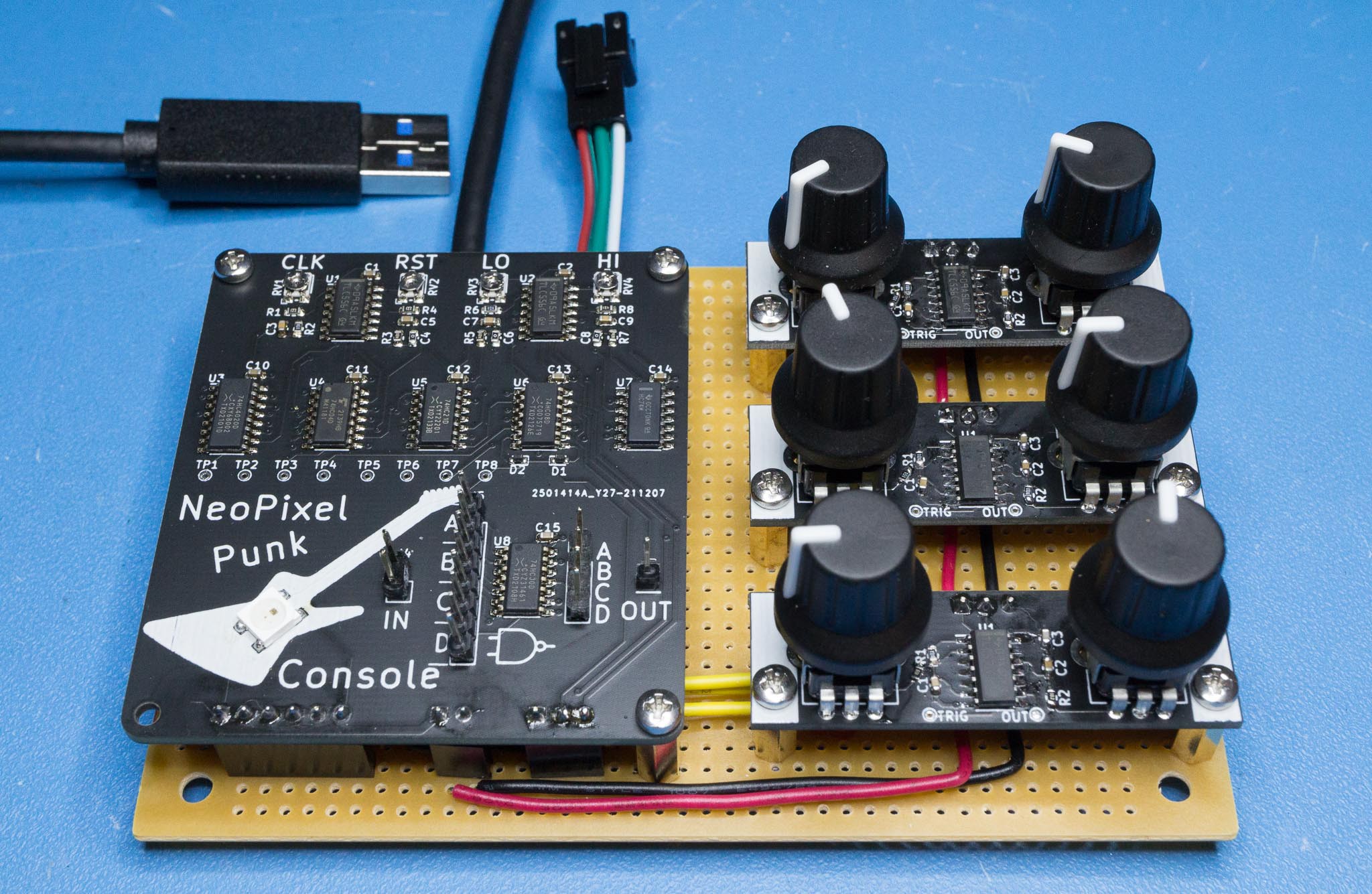
The circuit is split across several circuit boards. The RGB LED controller and mixing logic for the three oscillators are on the main PCB.

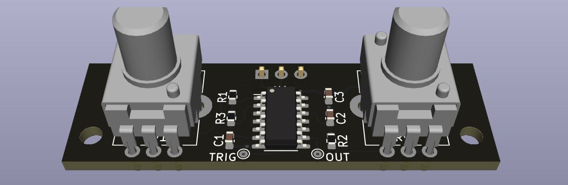
A separate PCB is designed for the oscillators. The LED and color oscillators are identical circuits with different values, so the same PCB design can be reused. Three oscillator boards were built, one LED oscillator and two color oscillators.
Perfboard is used to attach and connect the different PCBs.
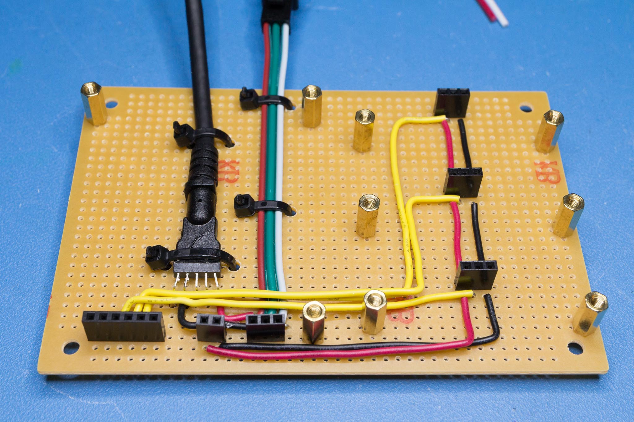
The thick black cable is a USB cable salvaged from a cheap USB hub. It provides 5V from a USB charger or battery pack to power the circuit and LEDs. The red-green-white wires belong to a pigtail cable that came with the RGB LED strip.
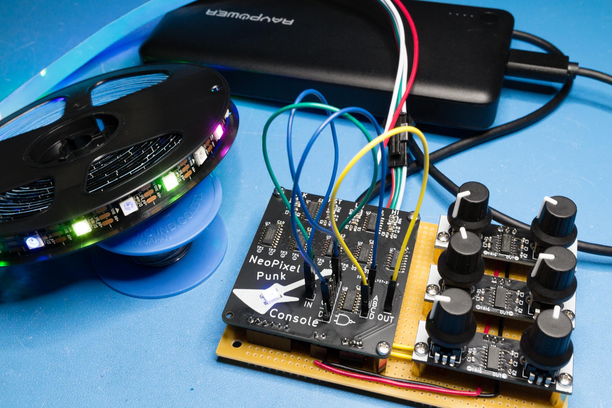
And here's everything hooked up to an LED strip and power bank.
The jumper wires route the input from the two color oscillators through two NAND gates, resulting in a logical AND (i.e. the color bit is 1 if both oscillators are 1).
Note that the PCBs shown in the photos are revision v1.0. The design as documented already incorporates various bodges that the keen-eyed reader may have spotted.
CONCLUSION
Does it work? Yes it does!
However as feared, control of the color patterns is quite delicate. It is also almost impossible to get anything else than the primary colors, purple, yellow and white. And most LEDs that light up are fully turned on making them very bright.
A future design would likely replace the oscillators with something more analog, split into dedicated R, G and B channels, which would also require some kind of ADC.
But that's for another time. :)