 Adrian Studer
As mentioned in my previous update, I have a 16x16 RGB LED matrix that, unlike the LED strip and the 8x32 matrix, does not light up with the NeoPixel Punk Console.
I used an Arduino and the sample sketch of the Adafruit NeoPixel library to verify that the LED matrix is not defective, and that works as expected. So the issue is definitely caused by something that my circuit does.
NeoPixel is a brand name invented by Adafruit to cover a whole class of RGB LEDs that use the same protocol. The most famous is the WS2812, but there are also WS2812B, SK6812, and likely several more.
And indeed, despite having bought all my RGB LED toys from the same vendor/brand (BTF-Lighting) and being from the same product line (WS2812B ECO), they all use different LEDs!
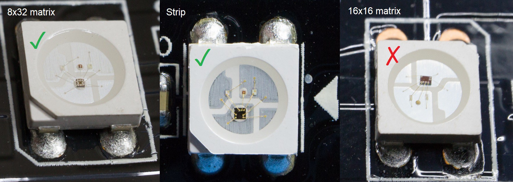
While they all speak the same protocol, #3 seems to be more pedantic about following the specifications.
My first thought was about timing or signal quality. But probing the data out pin on a few of the LEDs on the 16x16 matrix shows that the LEDs are recognizing, processing and forwarding 0, 1 and reset pulses as expected. So that doesn't seem to be the issue.
But while probing around, I noticed a glitch that may upset some NeoPixel variants: When the reset pulse is due (orange trace, RST_PULSE in the schematic), the NeoPixel Punk Console still sends out an extra pulse before going low (yellow trace, DATA_OUT in the schematic).
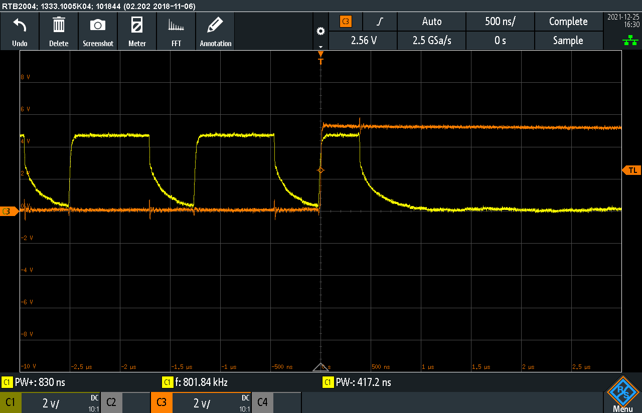
Side note: The negative edge of DATA_OUT is quite slow due to the diode-logic OR using a pull-down resistor. I tried a lower resistor value which cleaned up the signal but didn't fix the issue with the 16x16 matrix.
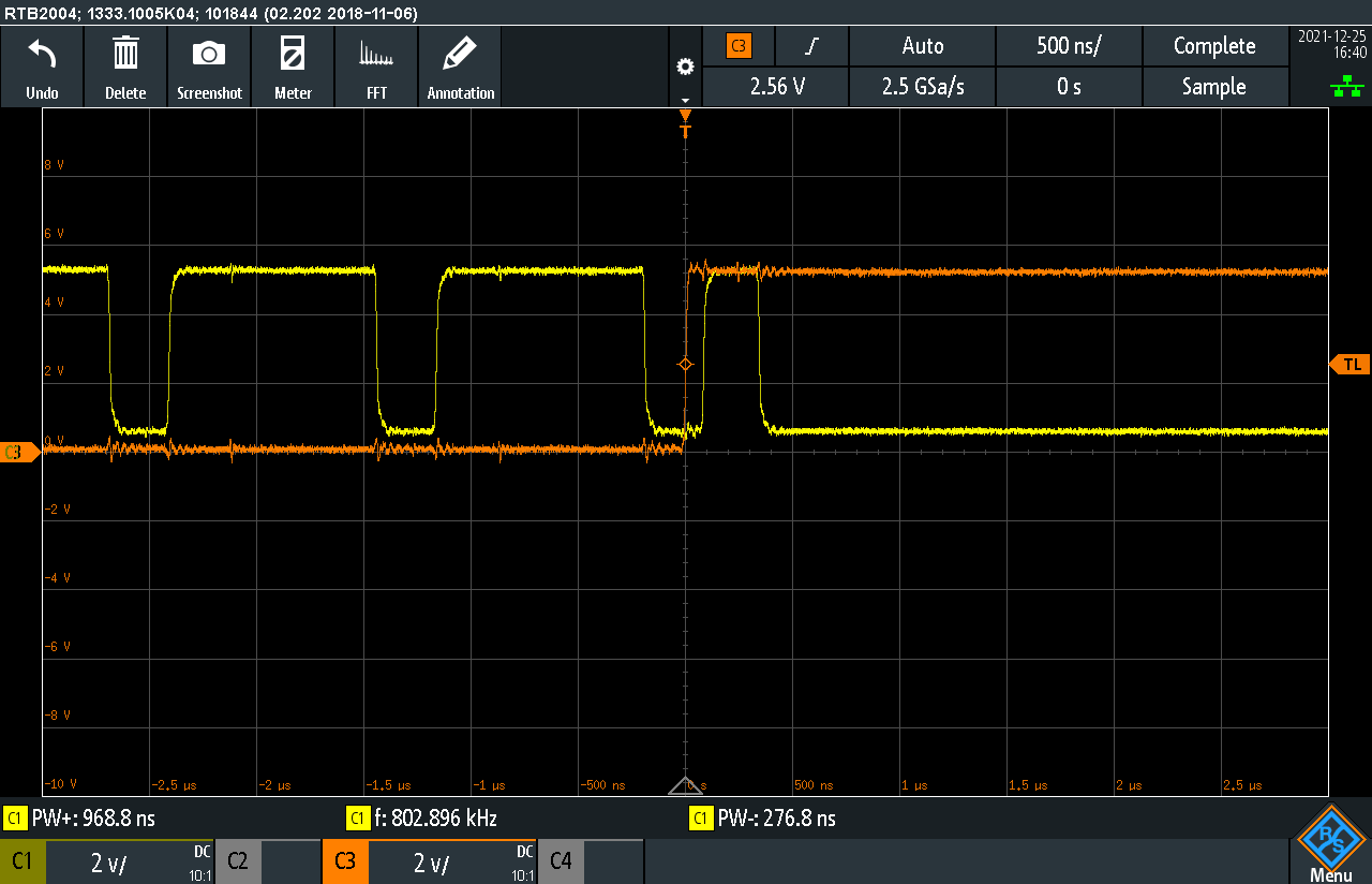
To force DATA_OUT low during reset, the inverted RST_PULSE is connected to the reset input R of the 555 timers generating CLK, LO and HI pulses. I expected this to force their output Q low instantly. But looking at CLK as an example (yellow trace), this is not the case:
My current working theory is, that the state machine inside the RGB LED used on the 16x16 matrix is interpreting this pulse differently than the others. For example, the LED could zero its "color" register at the start of each new 24-bit packet of pixel data, which in case of an extra 0-pulse like above would result in all LEDs staying dark.
To fix this glitch I plan to directly combine the inverted RST_PULSE with DATA_OUT through an AND gate. Funnily, that's how it's wired in my original sketch, but I tried to be smart and save a gate. 🙄
PS: I'm stumped why the 555 timers still generate a pulse while reset is already low. Any ideas?
PS2: Mysteries solved! See next log.
Discussions
Become a Hackaday.io Member
Create an account to leave a comment. Already have an account? Log In.