 IoT-devices, LLC
GGreg20_V3 is an inexpensive and useful device for checking the “purity” of:
- mushrooms,
- berries,
- vegetables,
- firewood, etc.
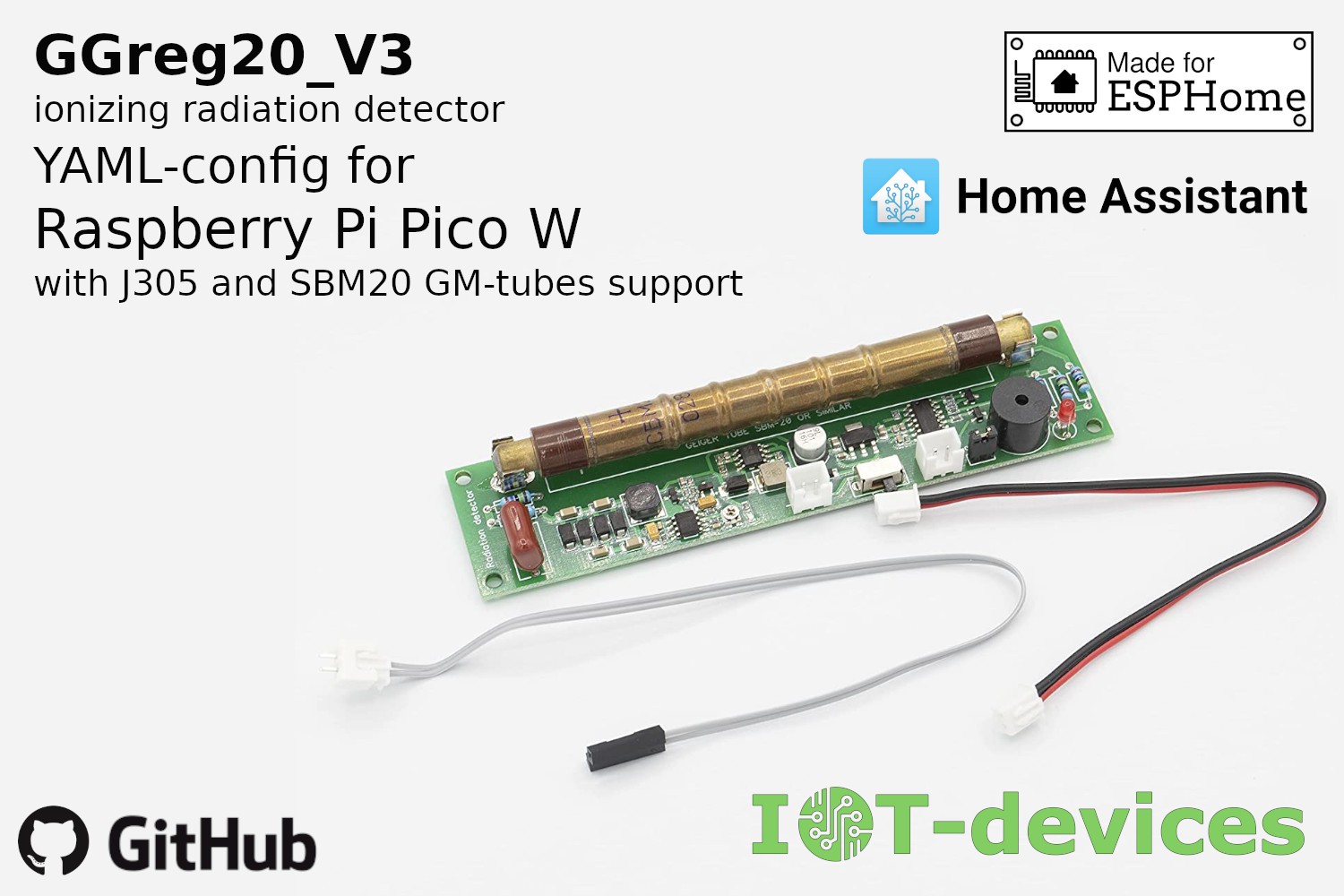
This module is useful for creating smart measurement devices for determining the power of ionizing radiation indoors or outdoors, and is available in both portable/pocket style and stationary mode. The only thing you need to start measuring ionizing radiation with the GGreg20 is any microcontroller that can count the number of pulses per unit time on GPIO.
Specifications
- Module dimensions - 30 x 126 x 12 mm. Weight 30 g.
- Power supply:
- a rechargeable battery or a battery: 1 cell Li (3.7V) battery, 2 cell Ni (2.4V) battery, 3 cells (4.5V) battery connecting to port "Bat";
- a 5 Volt charger.
- Power supply of the SBM-20 tube is a built-in adjustable high voltage DC-DC converter. The target voltage level of 400 V is regulated by a potentiometer. The module is fine-tuned and ready for use.
- Consumption current - 18 mA at 5V or 30 mA at 3.7V via LiIon.
- GGreg20_v3 is compatible with the ESP8266/ESP32 logic signal levels (3V3 ACTIVE-LOW: 3 to 3.3V HIGH and about 0.7V LOW), and will work even with the 5V logic input.
Dimensions and Pin assignments
GGreg20_V3 module pin assignments are as follows:
- BAT - Power supply input 2.2V - 5.5 V;
- ON/OFF - Main switch on/off;
- OUT - Pulse output, active-low;
- BUZ - Buzzer enable jumper.
The dimensions of the GGreg20_V3 module are as follows:
- X: 126 mm;
- Y: 30 mm;
- Z: 12 mm.

Differences and compatibility with previous versions of GGreg20
| Names of characteristics | GGreg20_V3 (NEW) | GGreg20_V1 | Improvement status |
|---|---|---|---|
| Design | monomodular | two-module | Improved |
| Stability of detection results | In the range of 2.4 - 5.5 volts (see note 2 and note 3) | Only at 5V supply voltage (uUSB input) | Improved |
| Power supply voltage range | 2.2 - 5.5 volts (see note 2 and note 3) | 3.7 - 5.5 volts | Improved |
| Autonomous power supply | 1 cell Li (3.7V) or 2 cell Ni (2.4V) or battery 3V or AC / DC adapter 2.4 - 5.5 V (see note 2 and note 3) | 1 cell Li (3,7V) or 3 cell Ni (3,6V) or 3 cell battery (4,5V) or AC/DC (5V) adapter | Improved |
| Complexity of the integration | Two connectors and one jumper (total 6 pin) | Three connectors and a jumper (11 pin in total) | Simplified |
| Protection against connection errors | Key-protected connectors are used and a Schottky diode is installed (see note 2 and note 3) | Not provided | Improved |
| Design and size compatibility | Same, except placing the power switch | - | mostly unchanged |
| Current consumption | near 30 mА | near 30 mА | no change |
| Calculation formula | - | - | no change |
| Measurement accuracy | 20% | 20% | no change |
| User interfaces | LED, buzzer, Output connector | LED, buzzer, Output connector | no change |
Note 1 The GGreg20_V2 module version has not been included in the comparison because it was developed for other design solutions (and did not provide space for the SBM-20 tube on the module board).
Note 2 The module board has a default protection diode against erroneous pole reversal when connecting the battery. Such protection will be appropriate despite the fact that it slightly narrows the voltage range of the input power supply which will be 3-5.5 volts.
Note 3 If you want to power the GGreg20_V3 from a 2.4 volt source, you need to short the Schottky diode shown in the photo with a wire or replace it with a 0 ohm resistor. Note, however, that such a correction will disable the module's reverse polarity protection.

Switching-on and measurements
This module is ready for use. The GGreg20_V3 modules are adjusted, configured and tested for compliance with the declared technical data before being shipped. Any adjustments or settings made by the customer may damage the module or introduce technical inconsistencies.
Connect the power input from the selected power source.
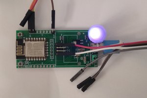
Turn on the power supply. After 10-15 seconds, you will hear a sound and see light signals when the active particles enter the tube.
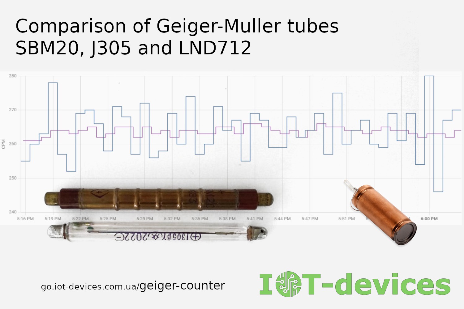
At normal background radiation, the tube registers and generates...
Read more »


 strange.rand
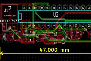
 Michael O'Toole
Thank you for your interest in our development and for your questions! We're glad you noticed the coolness of this part of our project.
But this product is not an Open Hardware project and we do not distribute the complete schematic of the devices.
Currently, you can purchase the ready-made GGreg20_V3 module. Or, if you want to purchase only the DCDC_3V3_400V_V1 high voltage module separately, for your own Geiger counter module, please wait for it to be back in stock.
Here is the product address of the high voltage module:
https://www.tindie.com/products/iotdev/dcdc_3v3_400v_v1-high-voltage-module/
Follow our updates there, or on our Twitter:
https://twitter.com/iotdevicescomua
Have a nice day!
Best Regards,
IoT-devices LLC Team
Kyiv, Ukraine, Europe