 Michael Wessel
It's function is best explained with a demo video:
To build one, you'll need to get the listed components. You can either make your own Arduino-board like I did, or just use a standard Arduino Uno R3. R3 (or ATmega 328p) is the minimum though.
The Database of Quotes
The quotes are stored on SDcard - you can download the already processed DB from here https://cdn.hackaday.io/files/1831287834948352/db.zip and simply unzip it to a FAT32 formatted SD card. This SD card goes into The Inspirer.
I said "processed" DB - the DB is produced by a Python converter script https://cdn.hackaday.io/files/1831287834948352/readcsv.py which reads in the original quote CSV "database". From the CSV, it creates smaller, individual files, one per category. Note that some longer quotes need to be excluded by the script due to SRAM shortage on the ATmega side.
You can also easily add your own quotes and categories. If you do so, you must change the "mappings" file though, https://cdn.hackaday.io/files/1831287834948352/mapping.txt which first lists the total number of categories, and then the category names. For each listed category, there must be a ".txt" file with that exact name.
A quote file has the following structure; e.g., see marriage.txt:
187
A good marriage would be between a blind wife and a deaf husband.
Michel de Montaigne
Marriage is neither heaven nor hell, it is simply purgatory.
Abraham Lincoln
...
The number 187 is the number of quotes in that category / file (marriage.txt), and then one line for the quote and one line for the author. That's it - simple, right?
Usage & Setup Instructions
Well, I don't have a schematics for this one, and I don't think it's really necessary. You can set it up any way you like. Please have a look at this picture to get an idea:
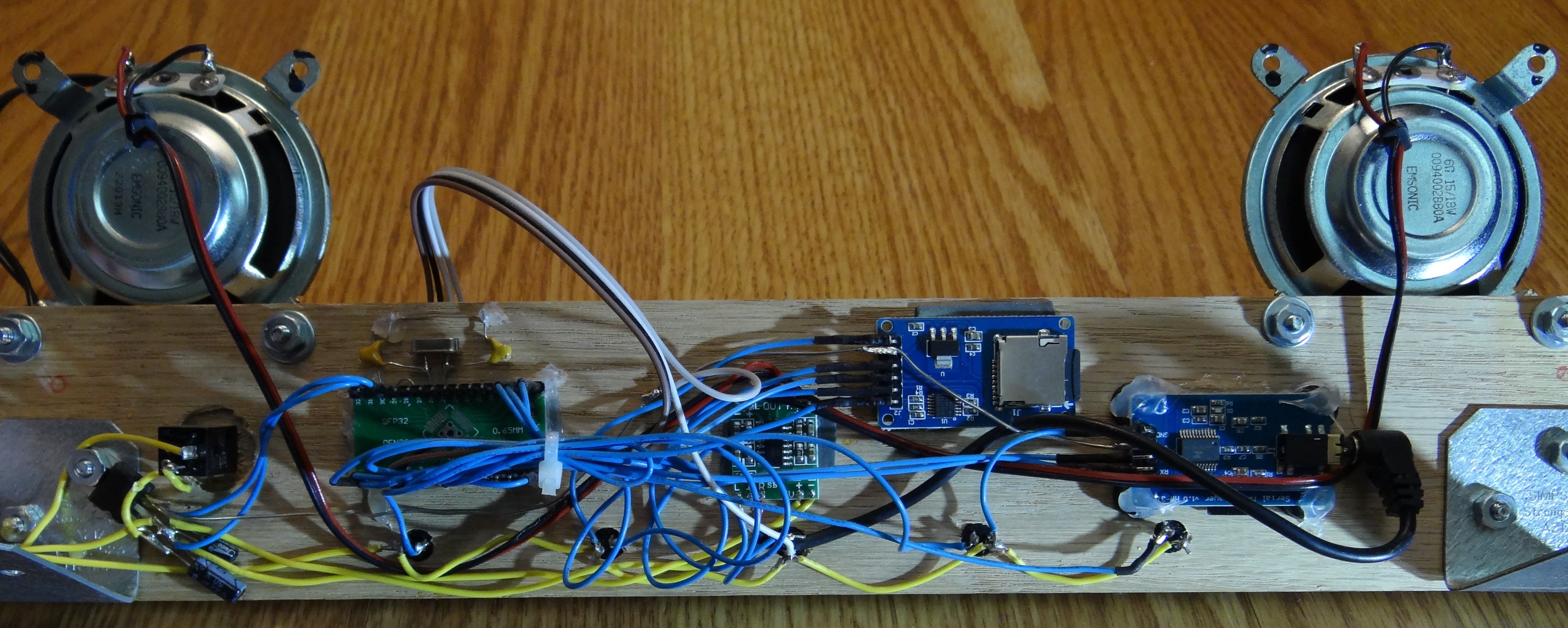
From left right, you see the LM7805 5V regulator and its 2 capacitors (100 uF and 10 uF), then the on/off switch, then the TQFP ATmega 328p with its 16 MHz crystal and 20 pF capacitors on a TQFP-2-DIP adapter board (the ATmega is facing towards the other side, so you can not see the chip, only the board), then there is the PAM audio amplifier, the SDcard module, and finally the MP3 module. Two loudspeakers, and the row of 5 buttons at the bottom. Held together with hot glue and extra strong double sided Scotch mounting tape.
The middle button is the SHIFT button; then, to the left of the SHIFT button, there is the "Previous Song" and the "Next Song" button. To the right of the SHIFT button you'll find the "Fix Category" and "Random Category" buttons. The idea is that upon power-up, The Inspirer delivers random quotes from random categories. However, if it comes up with a category you really like, you can push the "Fix Category" button to get more quotes from that same category, until you specify your own category, or push the "Random Category" button again. If you hold down the SHIFT (middle) button together with the just explained buttons, you will get "Previous Category" and "Next Category", as well as "Volume Up" and "Volume Down" as alternative button functions.
Here are the required pins; please refer to the Arduino pinout, the code snippet below, and my explanations below for further clarification:

//
// Buttons GPIO Pins
//

#define NEXT_SONG_NEXT_CAT_BUTTON 14
#define PREV_SONG_PREV_CAT_BUTTON 15
#define RND_CAT_VOL_UP_BUTTON 16
#define FIX_CAT_VOL_DOWN_BUTTON 17
#define SHIFT_BUTTON 2

//
// MP3 player Pins UART 0 / 1
//

#define TX 0
#define RX 1

//
// SD Card Chip Select = 10 ( PB2 )
//

#define SDCARD_CHIP_SELECT 10 // PB2

//
// I2C Addresses of the 4 Adafruit Alphanumeric Backpacks
//

disp1.begin(0x74);
disp2.begin(0x71);
disp3.begin(0x70);
disp4.begin(0x72);
Note that you will need to assign unique I2C addresses to the 4 different Adafruit Alphanumeric Backpacks. As you can see in the code snippet above, I have used 0x74, 0x71, 0x70, and 0x72 (kind of random). This will require setting a SMD jumper on the backpacks for address selection. Check out the Adafruit site (link below) for more details about this jumper setting process:
Then, with unique I2C addresses assigned, you can just daisy-chain the alphanumeric backpacks together. The I2C SDA / SCL pins are called A4 and A5 on the ATmega 328p Arduino, see diagram above.
The Serial MP3 Player needs RX and TX, or Arduino pins 0 and 1. Again, see the diagram above.
For the SD card module I have selected pin 10 as SD select pin. As it is a SPI module, you'll need to use the usual MISO / MOSI / SCK pins, which are 12 / 11 / 13 on the ATmega 328p.
For the push buttons, they need to be NO (Normally Open) buttons, and they are just configured using the ATmega's internal pull-ups. So when you push a button, it just connects the corresponding pin to GND. The GPIO pins are 2 for the SHIFT button, and 14 to 17 for the other buttons, also see the code snippet above.
That's really it. It is quite straight forward to set this up.
Congrats, you have taken your first steps toward fighting the winter blues!