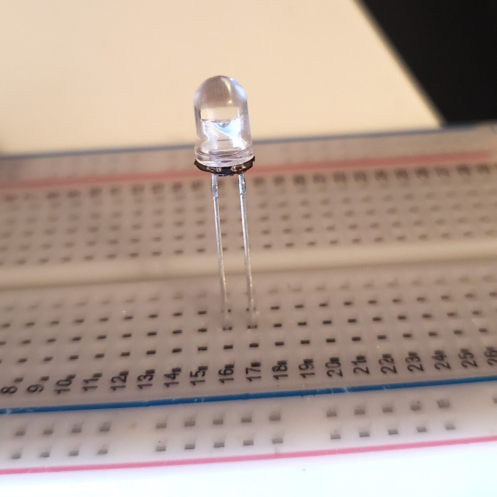
Close
0%
0%

A different kind of programmable LED

I still can't believe it's working.

Similar projects worth following
I attached a very very small circuit to a through-hole LED to run a custom programmed pattern, similar to a candle-flicker LED.

The Concept

A flicker LED is an LED that flickers. More specifically, it is a drop-in replacement for a conventional LED—no need to change the current-limiting resistor, no new calculations for forward voltages, it works just the same as a conventional LED. And they're cheap, too! If you want an LED that flickers like a candle (or one that blinks at a set frequency and duty cycle) you are set for life.

But what if you want a different LED light pattern? In my specific case, I want an LED that turns on like a struggling fluorescent bulb. Or one that stays off most of the time, then suddenly lights up the room like lightning. Or a pseudo-status LED that blinks at random frequencies to trick the viewer into thinking some complex process is running. Or...anything, really. A programmable LED!

Do programmable LEDs like this exist? Obviously the WS2812b and similar LEDs exist, and those are frequently called "programmable LEDs". But those are pretty different than, say, a flicker LED. You still need a controller of some variety to tell the WS2812b what pattern to perform, which is not the case for a flicker LED, and not the case for the LEDs I'm envisioning.

The Circuit

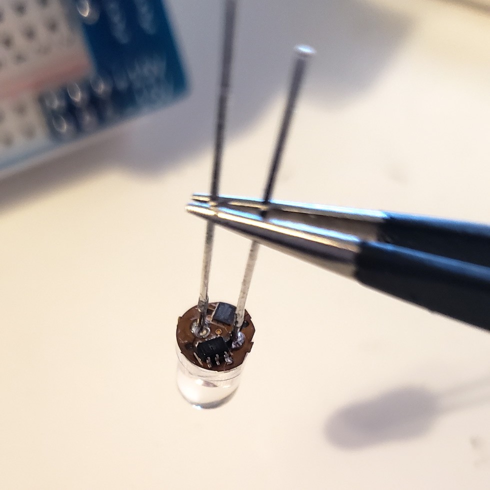
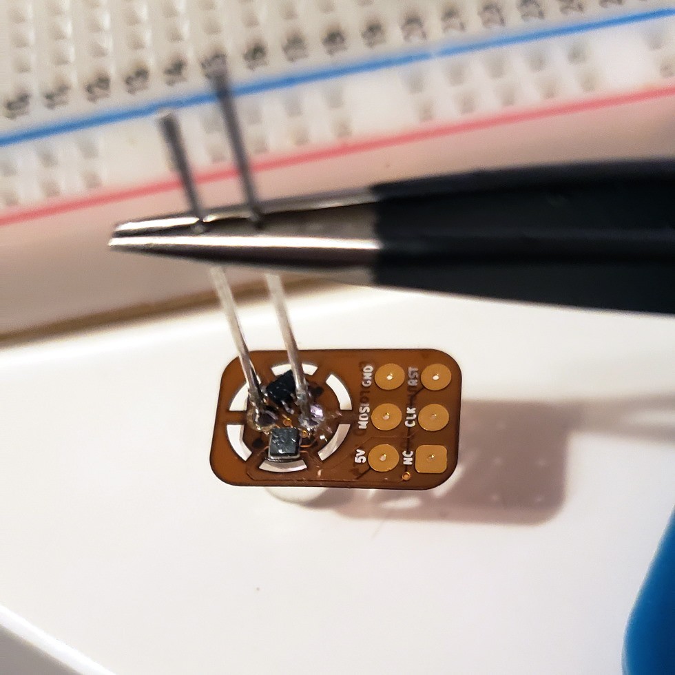
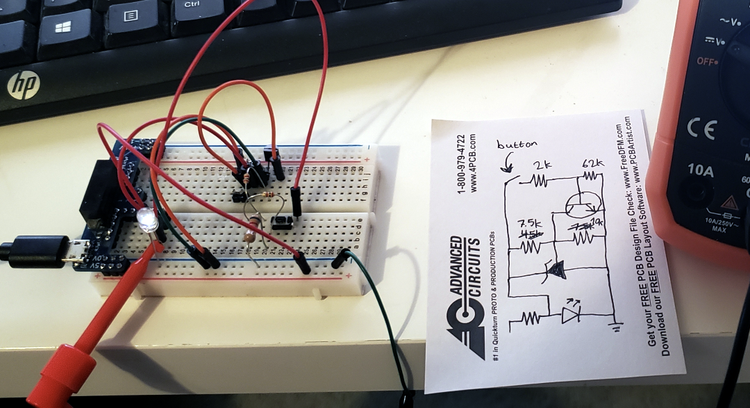
So can it be done? Without designing a custom IC and embedding it in a custom LED casing? I need a solution compatible with a stock LED. And that means the solution needs to exist in parallel with the LED. I'm envisioning a small PCB nestled underneath a 5mm through-hole LED. Soldered in place between the existing legs, no cuts or modifications to the LED itself.

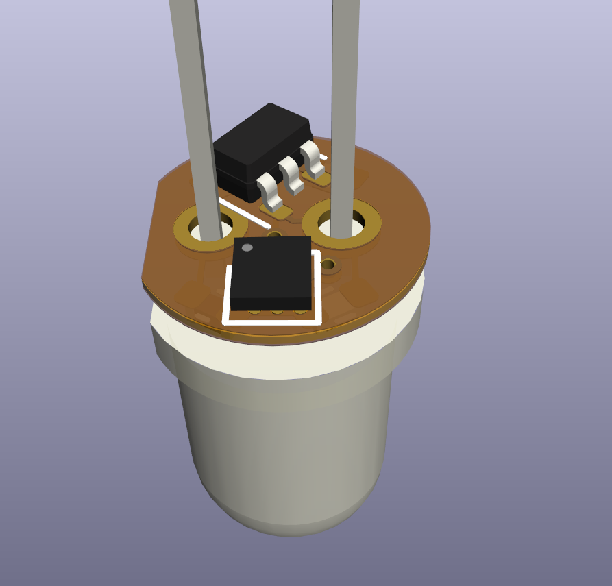
What microcontroller is small enough to fit under a 5mm through-hole LED? I know of two: the WLCSP-12 ATtiny20 (1.55×1.43 mm) and the WLP-16 MAX32660 (1.55×1.57 mm). It's true that I've been meaning to get better with ARM systems, but for now I'll stick with the more familiar AVR-based ATtiny20.

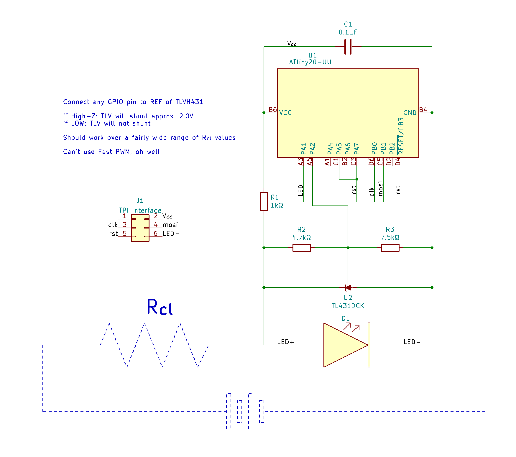
Both those microcontrollers require at least 1.8V to operate. A white LED drawing between 1 and 20 mA will have a forward voltage in roughly the 2.4 - 3.1 V range. That means a microcontroller in parallel can be powered while the LED is on! However, if the LED shuts off, the voltage across it drops to 0V and the microcontroller will shut off as well. To get around this, we can make the LED super dim instead of completely turned off. If we use a shunt to get the LED forward voltage into the 1.8 - 2.0 V range, the microcontroller can stay on while the LED light output is undetectable. A TLVH431 adjustable shunt lets us keep the same forward voltage, regardless of if the shunt is carrying 1 mA or 20 mA, which makes things more consistent than a Zener diode can do.

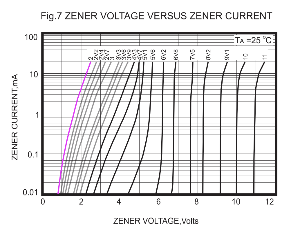
My original plan was to shunt current around the LED using a BJT driven by an I/O pin on the microcontroller. This would be paired with a Zener diode to keep the LED voltage at at least 1.8V, to ensure the microcontroller has enough power. There were some issues with this approach! For one thing, I learned that low-value Zeners have much more variation in their breakdown voltages. A diode sold as a 1.8V Zener might, at a current of 10 mA, have a breakdown voltage closer to 2.6V; this wouldn't dim the LED at all!

Another issue was the transistor. I didn't realize that I could sink ~20 mA directly into these microcontrollers' GPIO pins! In fact, the ATtiny20 GPIO can source/sink 40 mA, and the MAX32660 can do 25. This means the current being diverted around the LED can go through the microcontroller, instead of an external transistor. Thank you to [cpldcpu] for pointing this out to me! I don't know what led me to think that a BGA ATtiny could handle less current than SOIC or DIP equivalents. That set off a cascade of design adjustments that led to the current very-low-component-count design.

Putting it together

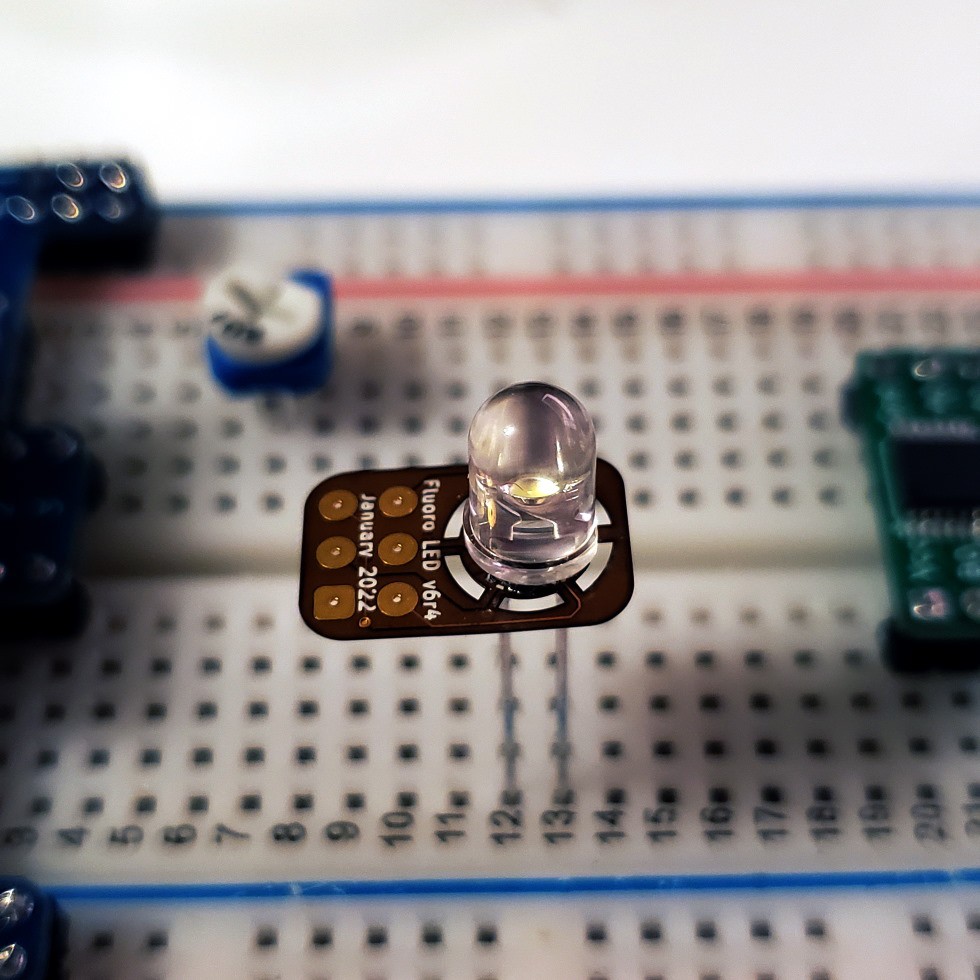
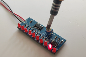
It's working! Here is a video of the flicker in action. The flicker animation is a port of one kindly provided by Emily Velasco, which you can obtain in the code/ folder of the repo.

As you can see...

Read more »

  • IT WORKS

    Sam Ettinger02/08/2022 at 01:40 0 comments

    Check out this video! It's working!!

    I assembled the wee PCB Sunday night, but it had an odd behavior, never turning on at all during the "flashing on and off" portion of the code. My first guess was that it had something to do with the 47kΩ and 68kΩ resistors that I used instead of the expected 4.7kΩ and 7.5kΩ, but the TLVH knowledge base suggests that shouldn't change anything except at particularly low currents. In my shower thoughts today I realized it could be the pin that I'm using for ADC measurements. The pseudorandomness of the flicker comes from taking multiple consecutive ADC readings on floating pin, and only keeping the least significant bit each time. Maybe a solder blob under the chip was influencing the ADC readings? So I switched to the one remaining spare pin for ADC readings and IT TOTALLY WORKED NO OTHER ISSUES yessssssssssss

    The git repo is updated. I still want to tweak the animation a little more before I cut the LED loose from the programming jig.

  • Protoboard success!

    Sam Ettinger01/24/2022 at 07:43 0 comments

    I just updated the git repo and project description to reflect the new version that I've been testing. The circuit has a much lower part count now, just four passives and the two ICs. The tradeoff is that the microcontroller GPIO pin must never be driven HIGH. When it's driven LOW, it shorts half the resistor divider for the TLVH431, which causes the TLVH431 to send its Vout as high as possible. When the GPIO pin is set to its High-Impedance state, the resistor divider sets Vout to 2.0V and pulls current away from the LED (without shutting off the microcontroller in the process). Driving the GPIO high would push Voutdown to 1.24 V which would definitely shut off the microcontroller.

    Pictures are in the updated project description! PCBs should arrive in a week!

  • Diode disappointment, new design, old designs

    Sam Ettinger01/15/2022 at 00:25 0 comments

    tl;dr The previous design seems less feasible now, but it inspired another, and also I'm revisiting a design from 2018


    I made a development board to experiment on, take measurements, and do things that would be impossible on the 5mm-diameter version. There are multiple values of LDO (including no LDO), multiple Zener diodes (including a TLVH431 adjustable shunt), and best of all, the schematic is right there with easy-to-reach test points!

    A microcontroller isn't necessary for tests—there's a pushbutton to mimic the GPIO. With the 1.8V LDO and 2.1V Zener diode selected, pressing the button does shunt current around the LED. Current through the LED drops from 17mA to 2mA, still illuminated but much much dimmer. Using the TLVH431 adjustable shunt when it's set to about 2.0V, the LED drops even further, to an undetectable 0.5mA current. Awesome!


    Unfortunately, using the actual 2.0V Zener diode does not work. Why? I did not realize how dramatically the Zener voltage increases with current. Here is the relevant graph from my 2.0V Zener's datasheet (I highlighted the relevant curve and faded out the nearby ones to make the grid easier to see)

    These Zeners in tiny packages with low voltage values may be rated for 200 mW or more, but when an LED's worth of current goes through it, the reverse voltage goes much higher than the stated value. This renders them useless for shunting current around the LED. I had no idea this happened to small Zeners! I thought I had four faulty values, from three different manufacturers! Now I know to look for this quirk in the future, I suppose.


    So what do I do if I want to shunt 20-ish milliamps at 2-ish volts around an LED? One option is to keep using a 1.8V or 2.0V Zener diode, but in a larger package. That would mean inviting my arch-nemesis, the MELF, into my domain. I have no intention of letting that happen. Instead, I'm going to try sticking with the TLVH431, which comes in a SOT-363 (SC-70-6) package that juuuuust fits on the PCB in question. The shunt voltage is normally determined by a resistor divider; we can use a transistor to circumvent one of the resistors and programatically change the 431 voltage without many components. This seems to work pretty well, so far:

    I need to do some experimentation to find the right values for the passives that permit it to work with a wide input voltage range. Shamefully, I still haven't tried controlling any of these with an actual ATtiny yet. [daniel] helpfully pointed out that I would likely be better off with a low-pass filter than an LDO for the ATtiny, so that is another thing to fiddle with.


    While I'm at it, I may as well revisit a similar project from 2018. It's also a fluorescent-flicker LED, but not a drop-in replacement. I'll save that for another update, though.

View all 3 project logs

Enjoy this project?

Share

Discussions

Tim wrote 02/08/2022 at 07:44 point

Congratulations! Very cool project.

It looks like you are not making a "candleflicker-LED", but a "broken flourescent light-flicker-LED"?

  Are you sure? yes | no

Sam Ettinger wrote 02/08/2022 at 08:42 point

Exactly! It doesn't roll off the tongue, does it?

Thank you for all your input on the project! I am so grateful for the atmosphere of collaboration and support :)

  Are you sure? yes | no

helge wrote 02/08/2022 at 22:00 point

Liminal Light Emitting Device ... LimiLED

  Are you sure? yes | no

Tim wrote 02/11/2022 at 05:26 point

Glad that I could help a bit :)

Any plans for a version that communication with the outside?

  Are you sure? yes | no

Sam Ettinger wrote 02/11/2022 at 05:39 point

Re: a version with I/O -- Yes! I got a prototype working today which was surprisingly painless. But before I write about that, I have to write about the corollary-project* that enabled me to make the prototype today, ahaha

* I made my USBasp support HV-TPI protocol, that's all

  Are you sure? yes | no

Ken Yap wrote 02/08/2022 at 07:20 point

👍 Cool, now all that's left to be done is to get the circuit incorporated into the LED die. 🤞🏽

  Are you sure? yes | no

Sam Ettinger wrote 02/08/2022 at 08:55 point

Haha, please tell me if you know someone who can do that! Goodness, imagine if it could incorporate optical programming like this micro mote: https://hackaday.com/2021/10/04/snails-sensors-and-smart-dust-the-michigan-micro-mote/

  Are you sure? yes | no

Ken Yap wrote 02/08/2022 at 09:02 point

You'll see it some day. Reading about the project involving Solari networked clocks gave me the mad idea of a time display where you only have to send synchronising pulses every so often to make the LEDs light up or not, depending on their positions in the display. Given that everything connected with electronics has ground-rocketed in price over the decades, I don't think it's too fantastic to ponder. Remember you read it here first.

  Are you sure? yes | no

Ted Yapo wrote 01/18/2022 at 22:22 point

do you know how you will fab the PCB yet? it's too small for OSH Park; their minimum is 0.25"x0.25". I was thinking of making an array of tiny PCBs on flex, then cutting them out with scissors or even the proper size paper punch

  Are you sure? yes | no

Sam Ettinger wrote 01/18/2022 at 22:51 point

I need to update a lot of things on this project! Here is what my OSH Park order looks like: https://twitter.com/DHammarskjold/status/1483339176812564481

It's 8.8 mm by 13.6 mm, big enough to order but small enough that I feel guilty ordering it by itself, hah. I've got traces running over the "bridges" so I can put the ATtiny20 into its correct location, then program it using those pads, then assemble the rest of the board. Now to wait for those flex boards....

Also worth noting! The traces are 0.12mm (about 4.7 mil), well under the 6mil officially-supported size, but I've done this many times before and have yet to see a bad trace. I still haven't tried making vias on flex that are smaller than the official 10mil/20mil, I'm curious if anyone's tried that.

Re: arrays, I can't attach pictures to these comments so I will tweet at you in a moment

  Are you sure? yes | no

Tim wrote 01/15/2022 at 09:14 point

It's a really cool idea! 

I wonder, would it be possible to realize this in a slightly simpler way? There are microcontrollers that work down to 1.5V. If you shont two PN diodes in series to ground with one GPIO (or maybe only one diode), then  it should be possible to "short circuit" the LED.
No LDO would be needed for the MCU. If your are afraid of glitching it with the current transients you could add an RC filter.

  Are you sure? yes | no

Sam Ettinger wrote 01/15/2022 at 22:04 point

Thank you! Regarding the microcontroller selection, I was only able to get my hands on two that are small enough to fit under a 5mm LED: the ATtiny20 and the MAX32660, which list minimum operating voltages of 1.8 and 1.71 volts, respectively.

It would definitely be easier to use general-purpose diodes, I agree! I haven't tried feeding the diodes directly into one of the GPIO pins yet, I should do that, thank you for the suggestion! When I tried general purpose diodes feeding into the collector of the NPN transistor, I needed two diodes to keep the voltage high enough for the ATtiny20, and it couldn't dim the LED sufficiently in my opinion.

And, yes, I have since replaced the LDO with an RC filter :) Thank you for suggesting it though!

  Are you sure? yes | no

Tim wrote 01/23/2022 at 17:07 point

Btw, you could probably also implement powerline control using your approach, similar to the way it is done in these LEDs:

https://cpldcpu.wordpress.com/2022/01/23/controlling-rgb-leds-with-only-the-powerlines-anatomy-of-a-christmas-light-string/

(I found that quite interesting, may give it a go mayself).

  Are you sure? yes | no

Sam Ettinger wrote 01/15/2022 at 23:47 point

This got me thinking about another idea! I can get rid of the NPN entirely if I connect the TLVH431's REF pin directly to a GPIO pin, I think. Something along these lines https://i.imgur.com/VwvU1G5.png

Until you mentioned it, I hadn't considered sinking current through the GPIOs directly! I was very surprised to learn that they can source/sink 40 mA continuously, even in the WLCSP-12 package. That will make things so much simpler!

  Are you sure? yes | no

Tim wrote 01/16/2022 at 08:03 point

That would already be the luxery version. You could probably just connect a resistor to a GPIO and shunt it to ground. There just needs to be enough current to turn the LED off (or dimmer), so this would also depend on the LED series resistance. But let's assume the LED is driven at 20mA (which is quite bright for a candleflicker LED), then an GPIO should be easily able to drive enough current to pull the VLED below the needed voltage.

  Are you sure? yes | no

Sam Ettinger wrote 01/16/2022 at 18:28 point

(This is a reply to your last post, but I can't figure out how to reply directly to it, sorry!)

I see your point, but like you say, 20 mA is quite bright :) My intention is to make this as similar as possible to the candle-flicker LEDs, which function over a wide range of currents. If you feed the candle-flicker LED 3 mA or 20 mA, the flicker function operates equally well; just the max brightness changes. A fixed resistor would not give me sufficient range. If that means creating a "luxury" version, than so be it :)

  Are you sure? yes | no

Tim wrote 01/16/2022 at 21:28 point

Yeah, of course. It's much more flexible with a TL431. And it's tiny, too.

  Are you sure? yes | no

Sam Ettinger wrote 01/24/2022 at 07:23 point

(replying to your powerline LED control comment)

That is SO COOL! I would love to know more about how to make a microcontroller respond that way to periodic shutdowns, I don't think I've ever seen such a thing. I have been toying with other ways of programming an LED-mounted microcontroller; using the LED itself as a light sensor would be the most fun way, but that's far beyond my knowledge. It will be more relevant in my *next* "ATtiny20 on a 5mm through-hole LED" project, haha!

Also, I can't believe I didn't recognize your username sooner--your projects with the SOT-23-6 Padauk and the ATtiny10 are so good and definitely influenced my own path in hobby electronics! Again, thank you so much for all the feedback, I'm pleased to say that the breadboard version with no BJT is working quite well with a supply between 0.5 mA and 20 mA. Maybe another week or so till the real PCBs arrive.

  Are you sure? yes | no

Tim wrote 01/24/2022 at 18:02 point

It could be implemented like this:

https://hackaday.io/project/183709-reverse-engineering-powerline-controlled-rgb-light/log/202615-emulating-the-powerline-control-scheme-with-a-mcu

Glad you liked my articles! I really love optimizaing minimal designs.

  Are you sure? yes | no

Daniel wrote 12/20/2021 at 21:14 point

Cool idea, I didn't know they make these micros in such tiny packages :)

About your circuit, I'd be more worried about transients rather than changes in the supply voltage over a slightly longer time. And since LDOs are pretty terrible to filter transients at low dropout voltages, you should be better off by replacing it with a reasonably sized LC filter.

You should also consider, that in your current design the regulator's input cap will cause a current spike through the switching transistor when the switch closes. I guess this will be fine, but it probably exceeds the maximum rating of the zener or the transistor.

  Are you sure? yes | no

Sam Ettinger wrote 12/21/2021 at 02:02 point

Thank you very much! I have not thought this through very much, other than to determine if it is geometrically feasible. That is a good point about the LC filter, I will tool around with different values (and hopefully not damage any μC's in the process). I also need to experiment with a filter on the I/O pin going to the NPN gate, for PWM smoothing purposes, but maybe that would be less necessary with an LC filter on the μC power input pin.

These wee microcontrollers are so cool, right? :D I would love to find an excuse to use the MAX32660, but that feels like overkill for blinking an LED, haha!

  Are you sure? yes | no

Similar Projects

Does this project spark your interest?

Become a member to follow this project and never miss any updates