Close
0%
0%

rolling screw extruder

a concept extruder, using threaded rods rolling around the filament to extrude.

Similar projects worth following
Theoretically, this style of extruder could put lots more force on the filament due to its long contact area. However, there are several problems, like the possible twisting forces on the filament or the inconsistent steps/mm. The goal of this project is to create a prototype and play around with this style of extruder. Ultimately, I want to measure how much pulling force I can exert on the filament. It would be very cool if it could pull hard enough to snap the filament.

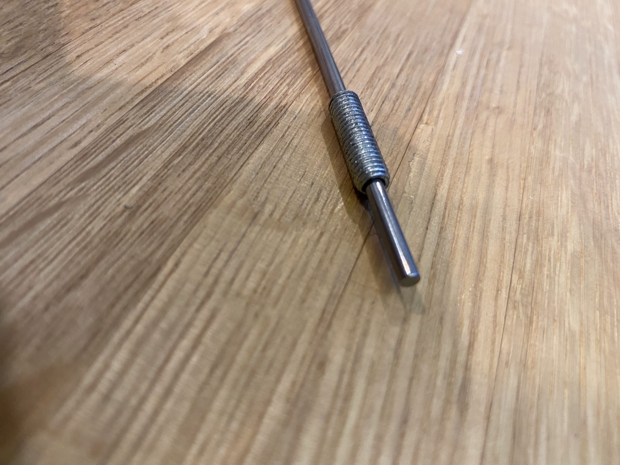
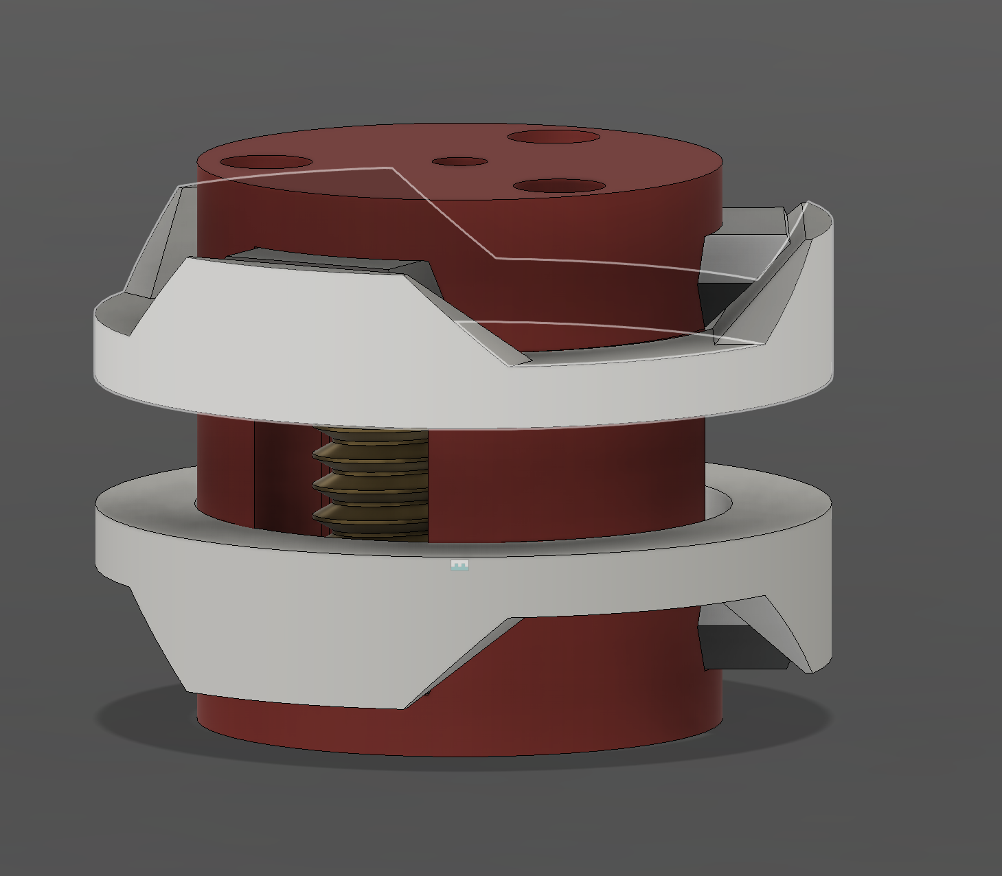
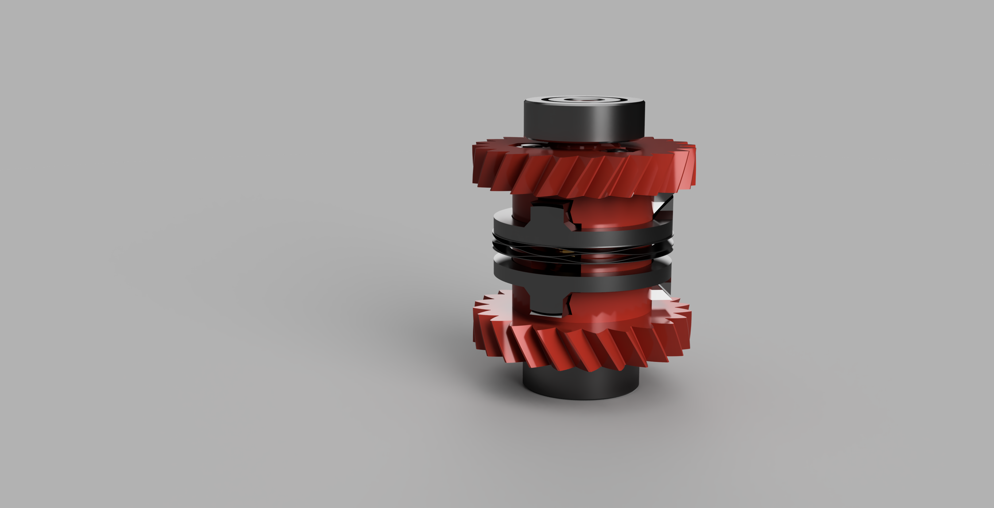
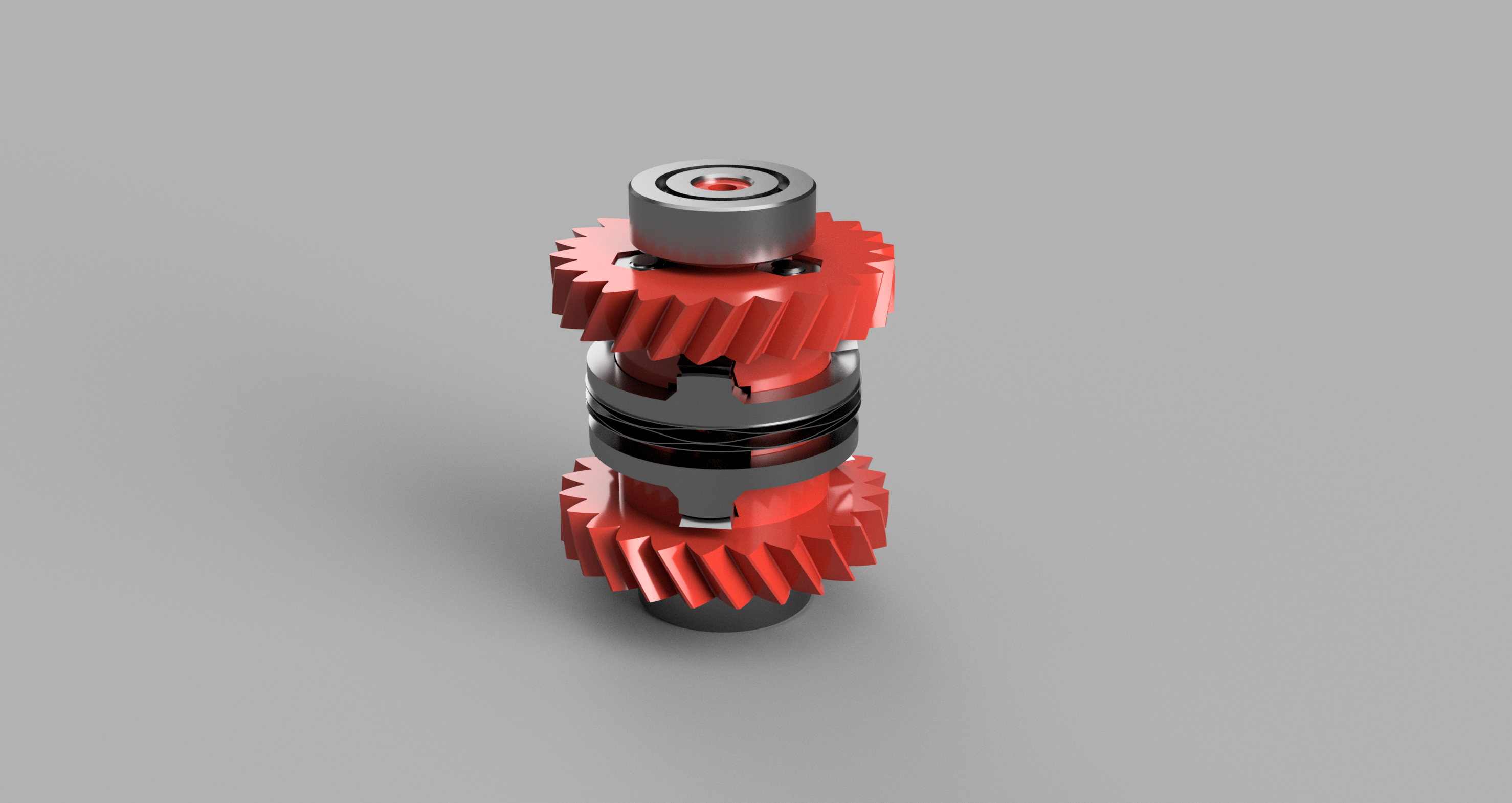
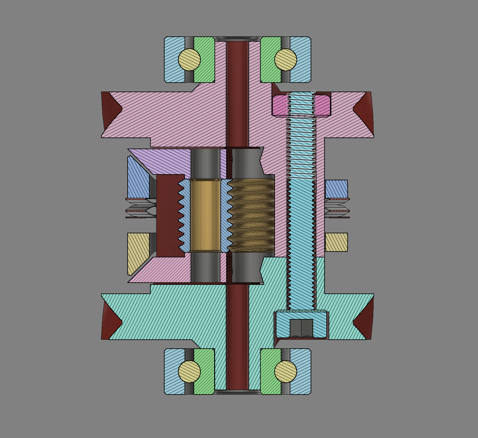
Many designs for this style of extruder that I've seen involve tilted rollers.  However, I don't have a lathe, so I need a different option.  I'm going for vertical M6 bolts instead of tilted grooved rollers, allowing me to fabricate it without a lathe.  Additionally, this means that the contact shape against the filament is linear, unlike the hyperbolic shape of the tilted rollers, allowing a more uniform interface.  

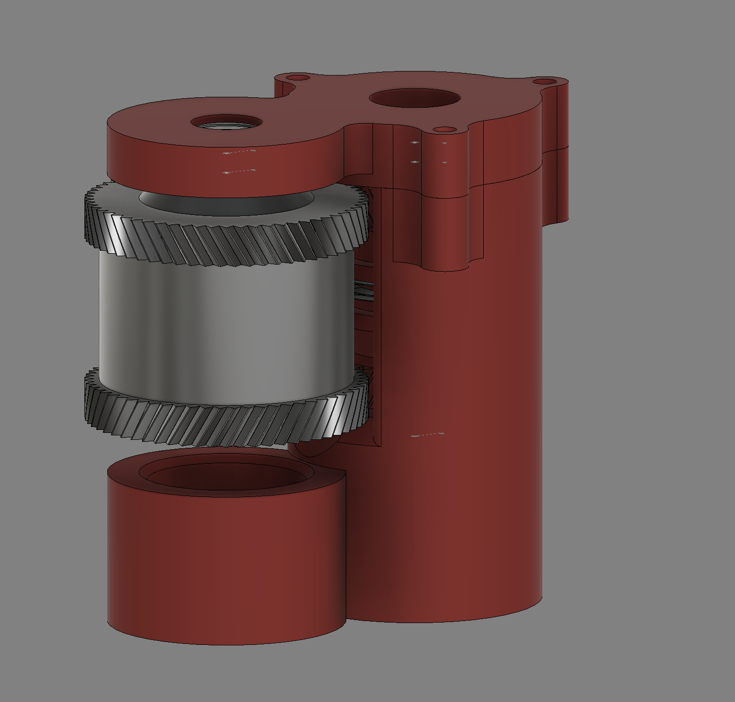
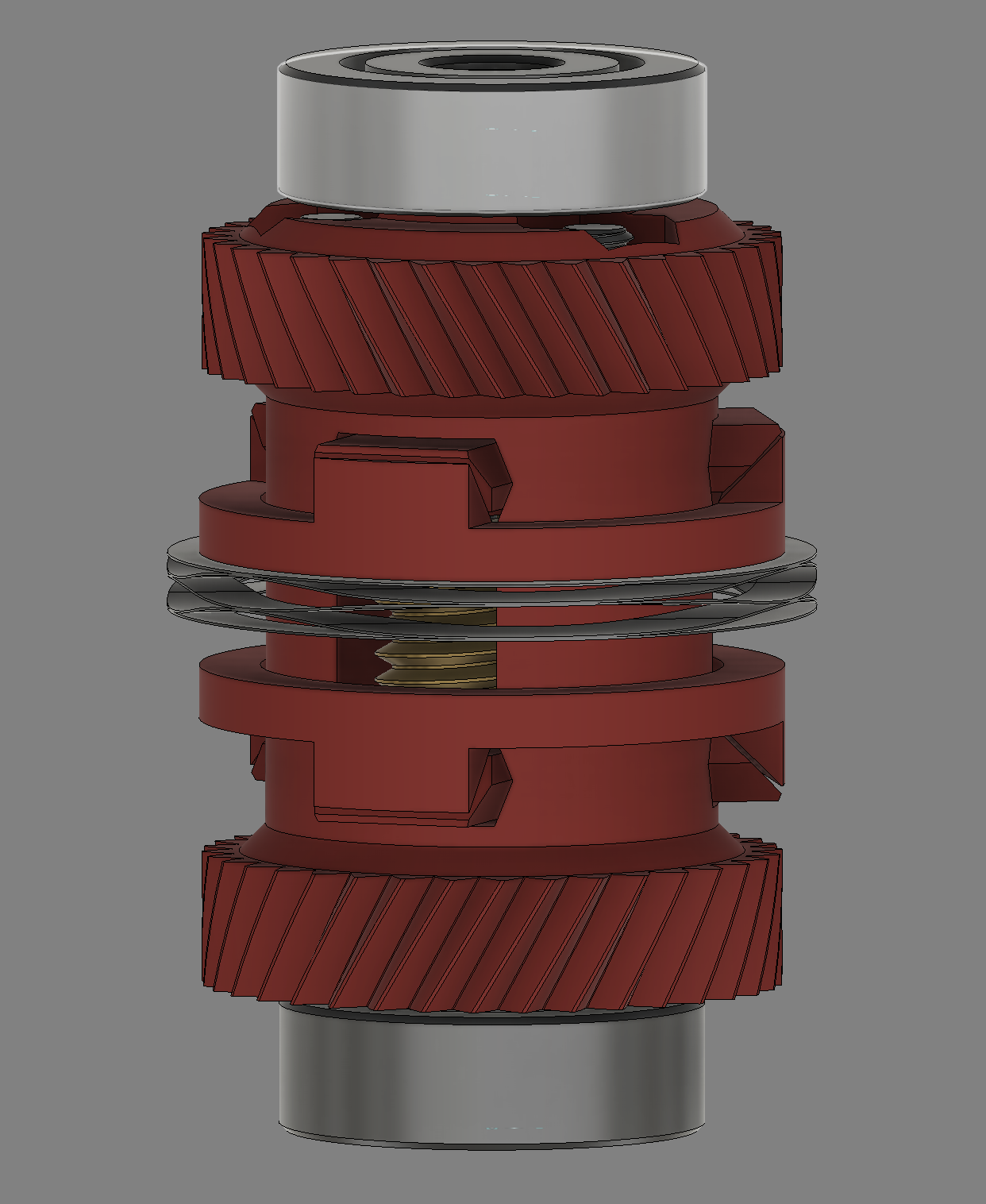
I'm also powering it with a brushless motor, because the screws mean I need high speed.  For 15 mm^3/s, the main body has to rotate about 1600 rpm.  Given that I want to use this extruder for high-speed printing, the main body has to be able to rotate at 6000+ rpm, which is way out of the range of okay speeds for stepper motors.

  • rollers made!

    ReidDye07/17/2022 at 19:59 0 comments

    So, I finally got around to making the rollers. Here's how I did it:

    1. cut the head off an m6 bolt

    2. put the bolt in the chuck of my drill press

    3. clamp the shortest, stubbiest drill bit I could find in a little clamping mount

    4. hold the mount down on the table so that the drill stays vertical but can move around laterally

    5. drill a small divot in the end of the bolt

    6. take the bolt out of the chuck and put two nuts on the end, tightened against each other. This makes a flat surface to sit on the drill press table while holding the bolt upright.

    7. use progressively larger drills to make a hole in the center

    This was after several attempts at other strategies, all of which failed. The two major things were:

    - just drilling and hoping it would be close enough

    - probing the part with a CNC router, then using that to drill the center

    But there were a ton of smaller things I tried as well that ended up not working. Anyway, the rollers are finally finished. I'm going to assemble and test it as soon as I can!

    Here's how it turned out. It fits great on the 1/8" shaft. The roller is much shorter than this; I need to cut it down still. And yes, I know I need a proper macro lens.

  • augh.... accuracy is hard

    ReidDye06/08/2022 at 15:28 0 comments

    This project has been put on hold, as I've been pretty busy lately with finals and robotics. But here's a quick update.

    The new design seems to be pretty good. The reshaped sliders work great, and the tensioning is the right strength, and it all moves smoothly. The enlarged gears are also big enough that they mesh smoothly. 

    The one problem has been manufacturing the screws. Even with a center drill eliminating wandering, I haven't been able to get a good center. I think I'm going to try to put the screw in the chuck of my drill press and use a jig to hold a center drill so that it can slide but not rotate - like a planar joint in fusion. Hopefully, this will self-center, and I can drill it normally after it is started. 

    If that doesn't work, my next plan of action is to use the CNC to drill a centered hole by measuring the position of the screw on several sides. However, the CNC (from my robotics team) isn't great for this kind of small-scale stuff, as it has significant backlash and no probing abilities, so I'd have to compensate for all of that manually.

    Another update will come once I manage to finally drill these holes... which might be a while :(

    And no, I don't have access to a lathe. My robotics team is an FTC team with no need for one, my school's FRC team is small and poorly funded (despite the exorbitant tuition), and my friends from another school who actually have a lathe aren't able to use it for outside projects. There is another team I could ask, who I will ask if none of the above strategies work, but ideally, this extruder should be accessible to us lay hobbyists without lathes. This is why I'm hoping the drill press idea will work - so you don't need a mill to make this.

    Anyway, wish me luck. I'll need it.

  • v3

    ReidDye01/13/2022 at 02:24 1 comment

    First log!  For context, here's v1 and v2 (sorry about table formatting, couldn't figure out side-by-side images):

    v1:

    V2, with housing and drive gear:

    V2, just the spinny bits:

    I just printed out all of the parts, and it's not going to work.  Here are my observations:

    1. the gear teeth are way too tiny.  They won't work.
    2. the sliding action of the parts that hold the screws is surprisingly smooth; the whole tensioning mechanism works better than expected
    3. the spring I bought (mcmaster 1561T43) is a little bit big.  It doesn't stay centered on the housing
    4. everything is really small.  Even with a jig, I still don't know how I'm going to drill a nice centered hole in the M6 screw.
    5. the hole in the center for the filament to go through came out way smaller than expected.  I designed it as 2mm, it came out 1mm.

    Taking those into consideration, I made V3:

    Here's a cross-sectional view.  I think this makes it easier to understand.  The small blue and yellow pieces on the left side of the middle are pushed apart by the spring (show compressed), which in turn push on the pink and purple wedge-shaped things.  These wedges hold on to the axles for the screws, so the spring maintains constant pressure on the filament.  

    Only the left side really makes sense here because the mechanism is repeated every 60 degrees.

    Here's what I changed:

    1. gear teeth are now twice as wide
    2. main housing is now 19mm diameter, to better fit the spring
    3. sliders are beefed up, and are >< shaped instead of <>.  This makes them more stable.

    I still need to design a v3 motor mount and housing, but that can wait until I know the base idea works.  Time to start printing!

View all 3 project logs

Enjoy this project?

Share

Discussions

mofka59rus wrote 04/01/2024 at 09:50 point

вы можете использовать термобарьер м6 у него внутренние отверстие на 4мм под тефлоновую трубку

  Are you sure? yes | no

arctype0 wrote 11/22/2023 at 00:32 point

I want to make it, but is there no more update?

  Are you sure? yes | no

ReidDye wrote 04/04/2024 at 19:47 point

sorry. It turns out it was really hard to get the precision needed to make the screws spin well, and at the speeds needed this, there were some problems with the screws rubbing on the plastic bits and heating up and melting the plastic.
Since the whole point of this project was to make this style of extruder without a lathe, I have decided to stop working on it, as all the parts I'd make to fix these problems would be lathe parts.

If you want the cad I'd be happy to send it to you. It might work if you can make the hole properly.

  Are you sure? yes | no

Similar Projects

Does this project spark your interest?

Become a member to follow this project and never miss any updates