Close
0%
0%

MKHBC-8-Rx

Generic purpose MOS-6502 based computer.

Similar projects worth following
MKHBC-8-Rx is one of the first projects I started to reactivate my hobby interest in hardware aspects of microcomputers (being a software guy/programmer by trade). It is an expandable architecture computer system built around passive motherboard with non-buffered CPU bus and buffered I/O expansion bus. Designed for MOS-6502 micro processor can be relatively easily adapted to different CPU-s with similar architecture (e.g.: Motorola 6809). Currently using a rudimentary monitor program as an O.S. written by Scott Chidester for his SBC (look for his project at 6502.org) and adapted to my hardware. Interfacing with the system is done by the means of character terminal via RS-232. I plan to build a Parallax Propeller based I/O card for it that will serve as VGA/video card, keyboard adapter and perhaps sound generator. I am having lots of fun with this one.

­MKHBC-8-R2 - Multipurpose 8-bit Homebrew Microcomputer. Design and Specifications.

1. Architecture of the system.

The system is intended as a hobbyist computing/microcontroller expandable platform. The CPU of choice is MOS 6502 compatible microprocessor. The design is a passive back-plane multiboard computer. It will consist of 2 buses:

  • 3-slot CPU bus for CPU, RAM and graphics cards.
  • Buffered 4-slot I/O expansion bus for other peripherals.

Other features:

  • Programmable 8-input prioritized interrupt controller.
  • Optional Real Time Clock with non-volatile battery backed SRAM for BIOS settings (DS1685).
  • Optional banked RAM (128 kB: 16 kB x 8).
  • Built in I/O port (6521/6821 PIA or 6522 VIA) for interfacing peripherals (joystick, I2C, SPI, serial keyboard, digital I/O).
  • Control panel with built in reset key, NMI reset key, power switch and (connected to built in VIA I/O port): 16x2 LCD (or better) display, buzzer and 2 programmable keys.

1.1. Memory Map.

$0000 - $7FFF: Base RAM, 32 kB.

$6000 - $7FFF: Optional Video RAM, 8 kB.

$8000 - $BFFF: Banked RAM, 16 kB space x 8 banks = 128 kB.

$C000 - $C7FF: I/O space, 8 slots x 256 Bytes = 2 kB.

$C800 - $FFFF: EPROM, 14 kB.

2. Back plane/motherboard.

Motherboard will consist of CPU bus with 3 64-pin slots for primary components of the computer system.

The primary components will include:

  • CPU card with EPROM, base RAM, reset/IRQ/NMI circuits and I/O address decoding circuits.
  • Optional RAM expansion card.
  • Optional RTC and battery backed SRAM card.
  • Optional graphics controller card.

The I/O address decoding circuit will decode 8 I/O address spaces, from which 4 (slots 0-3) will be used for internal system's built-in I/O devices (RTC, memory bank switch register, interrupt controller, VIA I/O port) and the rest of the slots (4-7) will be used in expansion bus.

Planned allocation for internal I/O slots in mother-board mode of operation:

  • Slot 0: RAM bank switching register.
  • Slot 1: RTC and non-volatile (battery backed) SRAM for BIOS settings (DS1685). The RTC circuit with backup battery will be assembled on the same CPU-bus card as banked RAM.
  • Slot 2: Prioritized Interrupt Controller. The circuit will be integrated on the motherboard, its control registers connected to the I/O bus.
  • Slot 3: I/O. 6521 (MC6821) PIA or 6522 VIA compatible I/O chip. The I/O pins would be buffered and exported to the 40-pin connector. Using this connector, external devices could be connected to the system. E.g.: general purpose control panel (keypad, LCD, LED-s, joystick ports, I2C,/CAN/SPI ports etc.).

Planned allocation for internal I/O slots in SBC mode of operation:

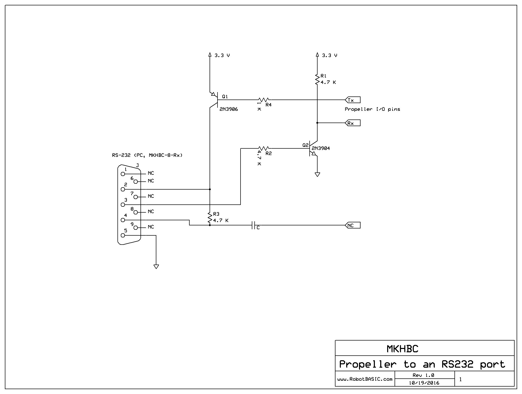
  • Slot 1: UART/RS-232.
  • Slot 3: I/O (PIA or VIA).

Motherboard will also consist of fully buffered 4-slot 40-pin I/O expansion bus, which is intended for expansion cards designed by user. That bus will use I/O slots 4 through 7. The bus will allow to address 256 registers in each slot (8 address lines), will have full data bus and all CPU signals as well as derived from CPU supporting signals (/OE, /WE). Each expansion card can be a source of IRQ interrupt signal.

Planned I/O expansion cards (for slots 4-7):

  • Mass storage controller (SD, flash, IDE).
  • SID (Commodore) based sound card.
  • UART/RS-232 (MC6850). - built

Planned CPU bus expansion cards:

  • Banked memory 128 kB + battery backed RTC and non-volatile SRAM. - built
  • Video Adapter (MC6847 VDG - Video Display Generator, but also considering more contemporary PICASO board, VGA controller with serial port as command input/output).

User input:

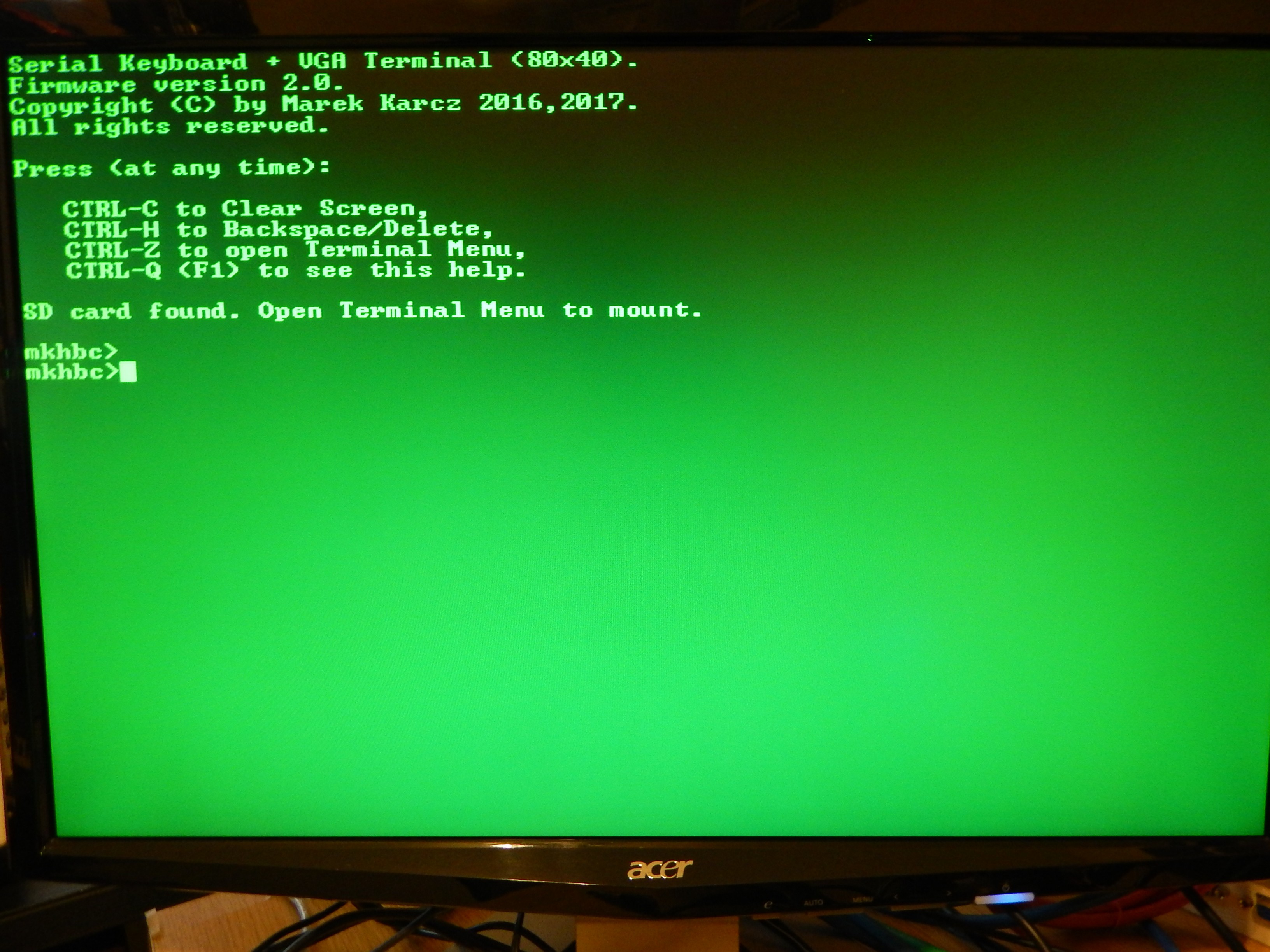
User input interface will be realized with full alphanumeric keyboard and digital joystick (C64, Nintendo, Atari compatible). The keyboard may be serial (UART, I2C) or classic matrix to be scanned in periodic interrupts generated by RTC chip DS1685 or timer in VIA adapter. If keyboard is to be serial, it must be the source of the IRQ interrupt which will read and store the input...

Read more »

Connections_RTC_BRAM.odt

Connections list for RTC / BRAM card.

text - 14.88 kB - 06/14/2017 at 04:20

Download

MKHBC-8-R2-CPU.sch

Schematic diagram of the computer's circuits (Express SCH).

sch - 298.13 kB - 06/12/2017 at 01:36

Download

ListOfParts_RTC_BRAM.odt

List of parts for the RTC/BRAM PCB.

text - 15.66 kB - 05/31/2017 at 06:36

Download

MKHBC-8-R2-Netlist.odt

Network (connections) list of the computer circuits.

text - 19.05 kB - 05/31/2017 at 06:36

Download

mkhbc.cfg

Configuration file for linker (cl65).

cfg - 263.00 bytes - 11/19/2016 at 16:48

Download

View all 17 files

  • Blueprints and source code now on github.

    Marek02/07/2018 at 05:38 0 comments

    I finally tooks some time to clean-up my project and code and publish it on github.

    In addition to refactoring the code I also added features :-)

    1) Interrupt service routine for RTC. (enabled periodic interrupts from RTC)

    2) RAM bank switching.

    3) RTC API moved to EPROM.

    4) KBHIT implementation.

    ...and more.

    Getting closer to the next development step which is to build general purpose I/O card for my system and connect some peripherals to it. I'd like to have a local standard console for UI instead of UART only. I want to connect some mass storage device to my system, some joysticks etc.

    I have quite long TODO list for this project, with many goals completed but some more difficult ones still waiting in queue.

    Some of them I list here:

    * Write library/API for mass storage.

    * Add copying memory ranges to enhanced shell app.

       mcp ADDR_FROM ADDR_TO ADDR_DEST

    * Build a prototype of a PIA or VIA I/O card on a breadboard. Connect to I/O slot #3.

    Create circuit schematic in the ExpressSCH program.

    Build on a breadboard.

    Test by attaching LED-s and switches to the I/O pins and write program to read/write values to the port.

    * Implement online (monitor) assembler and disassembler.

    NOTE: To be finally able to write programs in symbolic assembly directly on the MKHBC-8-Rx computer.

    * Add detection of RTC / Banked RAM card presence or lack thereof.

    NOTE: This should be easy. Method one - assume that RTC and Banked RAM are one. If memory test at $8000 - $BFFF range fails, there is no RTC as well. If it succeeds - assume RTC is also present. More difficult but also more accurate check would be to test RAM in the banked range and separately attempt to read the status register from RTC and determine each of these devices as separate resources.

    Also it would be nice to automatically detect that RTC is not set (e.g.: when battery fails or is not present) and ask user to setup time at startup.

    Currently with detection not implemented, system still boots up and works. Commands that rely on RTC or banked RAM don't freeze or crash, they just display incorrect information. I suspect that possibly commands 'rclk' or 'sleep' might possibly freeze without RTC/BRAM card present. I did not test these two. I will update this file once I do.

    * Add detection of UART card or lack thereof. Add detection of standard console (keyboard, graphics card) or lack thereof.

    NOTE: This may be more complicated than RTC / Banked RAM detection card. Bear in mind that this is currently the primary I/O for UI. No UART therefore means - no user interaction with MOS (monitor). However later there will be console present (keyboard, graphics/screen card) and UART will not be a necessary device.

    Summary of the system programming as of today:

    System programming / Operating System of MKHBC-8-Rx is divided into 2 parts:

    • Firmware, which resides in EPROM.
    • System programs, which are loaded to RAM via serial port.

    Firmware consists of hexadecimal machine code monitor, hardware drivers code, MOS-6502 mandatory vectors: Reset, NMI, IRQ and Kernel Jump Table.

    Firmware is implemented in MOS 6502 assembly language.

    Kernel Jump Table is a series of jump commands that redirect to code performing certain system functions.

    These jump commands are guaranteed to be always at the same memory locations, so the system programs using them don't have to be rebuilt each time the implementation of firmware is changed and some internal addresses has moved. The jump table is always in the same place jumping from the same locations to the same functions that they should perform, even if the functions themselves change the location in the EPROM due to code refactoring or relocation of binary code.

    The new entries can be added to the Kernel Jump Table though, so it is guaranteed to be backwards compatible.

    Theory of operation:

    When computer is started, the reset circuit holds...

    Read more »

  • Firmware for PropTermMK is now on Github.

    Marek06/20/2017 at 20:01 0 comments

    I published current version of firmware for my PropTermMK device on github: https://github.com/makarcz/proptermmk

  • NV RAM access added in DS1685 driver.

    Marek06/19/2017 at 18:31 0 comments

    I enhanced DS1685 RTC driver by adding API to access NV RAM.

    Details on my blog: http://6502cpu.blogspot.com/2017/06/update-on-mkhbc-8-rx-nv-ram-access.html

  • Finished building the RTC / Banked RAM card.

    Marek06/14/2017 at 05:02 0 comments

    Ufff! Took me 2 weeks, but finally finished my combined RTC and banked RAM card. As usual I used prototyping PCB and point to point soldering using enameled magnet wire. I used this part of project as opportunity to enhance my workbench with better soldering tools - quality soldering station, better wire cutters, PCB holder, solder wick, chisel tips, you name it. The job was more enjoyable thanks to that. I had a little scare at the end because the card didn't work right away, but it turned out to be a missed connection. Fixed it and it works now. I am pleased with the result and I'm looking forward to design and implementation of the User Interface I/O card. (keyboard, display, joystick, sound, mass storage etc.)

    Almost 300 soldering points - sometimes it is not fun. It is important to have good quality tools for this kind of work. I know, I am not good at it yet, but I am improving.

    This PCB holder proves to be a very handy tool.

    Ready to populate with IC-s and battery. Taking this opportunity to show off my new Hakko soldering station :-)

    The card is in the mother board here, slot B2, working fine.

    The test above shows that timekeeping and memory banking is working. Memory bank selection register is at address $C000, banked RAM starts at $8000. I also powered the computer down and back up and the RTC keeps the time. in a few days I will know if it is accurate.

  • Working on the RTC/BRAM PCB.

    Marek05/31/2017 at 06:34 0 comments

    I finally started working on the RTC/Banked RAM PCB. The technique used as on previous cards - point to point soldering on a prototype board. Lots of soldering, but now I have a gadget that makes this kind of work a bit easier and more pleasant.

    See for yourselves:

  • Serial port shield for Parallax Human Interface board.

    Marek05/21/2017 at 05:08 0 comments

    Some time ago I tried to make the serial port shield for my Parallax Human Interface board. The Human Interface Board uses many of the Propeller's I/O pins for VGA, sound, mouse, keyboard and SD card. However it still leaves pins P0-P7, and they are available on a header on top of the board along with 5V, 3.3V and Ground pins. Originally I used transistor based circuit from Propeller manual which was recommended by Parallax for programming the chip via RS-232, but unfortunately it didn't work for me. I spend hours debugging, building the equivalent on a bread board, making modifications and experimenting, but all to no avail. Here is the circuit that didn't work for me:

    This is how my shield looked like originally, inserted here on top of the Human Interface board:

    After many hours lost trying to make it work, I gave up, tested a different much simpler circuit and de-soldered the components to make a new one:

    This works just fine except occasional contact issues on the jumpers. I guess I need new jumpers because these are scavenged from some old board and seem to be loose and not making a good contact. I could have made permanent connections instead of reconfigurable jumpers, however I wanted to be able to re-configure hardware connections of Rx/Tx serial port pins to a different Propeller I/O pins if needed. I think this makes this simple shield much more practical.

    My development system just got a little bit better.

    After all that hard work, I fired up my MKHBC-8-R2 computer to have some fun playing BASIC game on my new shiny Propeller based terminal:

    See you later, I have a kingdom to run :-)

  • Propeller based serial terminal device with SD card as program storage.

    Marek05/16/2017 at 07:08 0 comments

    This little computer ultimately is going to be a standalone system. I am working towards this goal to hopefully one day cut the cord and get rid of the need for a PC as a host computer / cross-development platform. In the recent months I have been working on sort of an off-shot project that one day will help me complete this plan. I employed Parallax Propeller chip to build a serial terminal device for this computer. My requirements were as follows:

    * Dumb terminal with some subset of ANSI functionality with a keyboard (PC or self-made) and at least 80 columns x 25 rows display.

    * Mass storage (SD card) that would allow to transfer files to host computer (not PC, the MKHBC-8-R2) and save output from computer coming via serial port to a file on SD card.

    This serial terminal device is coming together nicely. It is not the last word though. In the final version I would like to have a Propeller based I/O card which serves keyboard input and display output, maybe some sound and joystick / paddle ports as well which interfaces with MKHBC-8-R2 via CPU or I/O bus instead of slow serial port. This serial terminal is sort of an intermediate step allowing me to get more familiar with Propeller chip.

    So far I was able to put together hardware and code to:

    * Connect to MKHBC-8-R2 via serial (RS-232) with 9600 baud speed.

    * Display hi-res text on VGA display.

    * Interface my home-brew retro computer keyboard (TI99/4A + 8052 micro as controller, serial interface similar to PS2) to Propeller and write my driver code. I also have a variant for PC keyboard, both presenting identical API interface, so all I need to do is load different driver to cog if I want to use a different keyboard, other code does not change.

    * Interface micro SD card to the Propeller and write Terminal Menu code which aids in sending contents of the text file from SD card to the serial port or dumping memory of MKHBC-8-R2 system to a file on SD card in the form of monitor memory write commands. Thus I can prepare file with monitor memory write commands on a PC or MKHBC system, store on SD card and then send them to the MKHBC-8-R2 system - a primitive way of of loading or saving data, but effective.

    * Implemented few ANSI terminal functions, like clearing screen or positioning cursor at specified column and row.

    I will soon post the code to github and update project with a link to it.

    On this screenshot I just uploaded Tiny Basic from SD card, ran it, then uploaded BASIC program listing from SD card effectively entering BASIC program into the memory just as I would do it from keyboard, then listed it and ran it.

    This is how the startup screen looks like. The 'mkhbc>' string is a prompt from the MKHBC-8-R2 computer received via serial port.

    My development system. I am using Quick Start board from Parallax with Human Interface shield on top for VGA and keyboard interfacing. To the right you see TI99/4A keyboard with 8052 controller (not visible, tucked in under the keyboard) connected to the Human Interface board. PC is the host for SPIN program development. The serial port interface is put together on the breadboard on the left of the Parallax board (just 3 resistors). The VGA monitor connected to the Human Interface shield is the one on the left that you can only see a corner of with the green glow.

    This is the Parallax Propeller USB Project board. This board will ultimately host the serial terminal device. I don't use it for code development for the serial terminal project because of the problem with powering keyboard from the USB port. To test code I needed to disconnect the USB programming cable and connect external power supply. For this reason I had to write the program to EPROM each time I made new build iteration if I needed to test it with the keyboard. Therefore I was afraid I was going to wear down the EPROM prematurely by frequent writing and brick the project board.

    On the project area I added serial interface, 5V power supply, keyboard mini-din socket, various headers and connections...

    Read more »

View all 7 project logs

Enjoy this project?

Share

Discussions

Bharbour wrote 06/14/2017 at 18:23 point

Nice Work!

  Are you sure? yes | no

Marek wrote 06/14/2017 at 23:26 point

Thank you.

  Are you sure? yes | no

Dylan Brophy wrote 05/12/2017 at 23:21 point

Looks like your project is coming far - farther than my Z80 computer.  Try adding some project logs.  Can't wait to see more :D

  Are you sure? yes | no

Marek wrote 05/16/2017 at 07:13 point

I always wanted to build and program my own Z80 based computer. I like CP/M. I used to want to have ZX Spectrum when I was a kid (ended up with C-64 later). One day I'm sure I will. For now I'm satisfied playing with CP/M mode on my C128.

  Are you sure? yes | no

Dylan Brophy wrote 05/16/2017 at 10:55 point

I wasn't alive during that time when those computers were around.  I love the Z80 because it feels simple, easy, and useful.  Really I don't want to run CP/M (Although that would be cool!), I want to make my own OS.  Btw, thankyou for skulling my Z80 computer :D

  Are you sure? yes | no

Similar Projects

Does this project spark your interest?

Become a member to follow this project and never miss any updates