There are a lot of dot matrix display projects out there ranging from chopped up LED strips glued to a board all the way to custom designed modular circuit boards. Given this project is geared towards high school kids with some basic electronics and soldering skills, the goal was to develop a robust modular system of building a large display that could be easily assembled without a lot of budget or complex skills. This modular system should facilitate wiring, power distribution and mechanical mounting while also allowing a fairly arbitrary panel to be easily constructed and programmed.
For those of you primarily interested in the end result, here is a quick video:
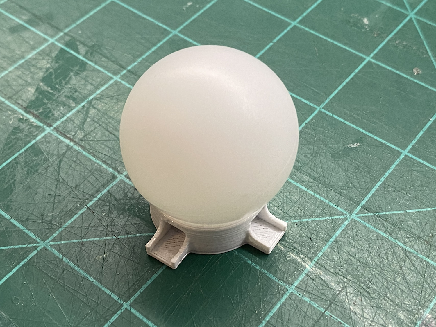
Since the goal was to use ping pong balls for diffusers the spacing between LEDs was set by the 38mm diameter of the balls. Given this doesn't line up well with existing LED strips I started with circuit board mounted LEDs which are easily found on Amazon:
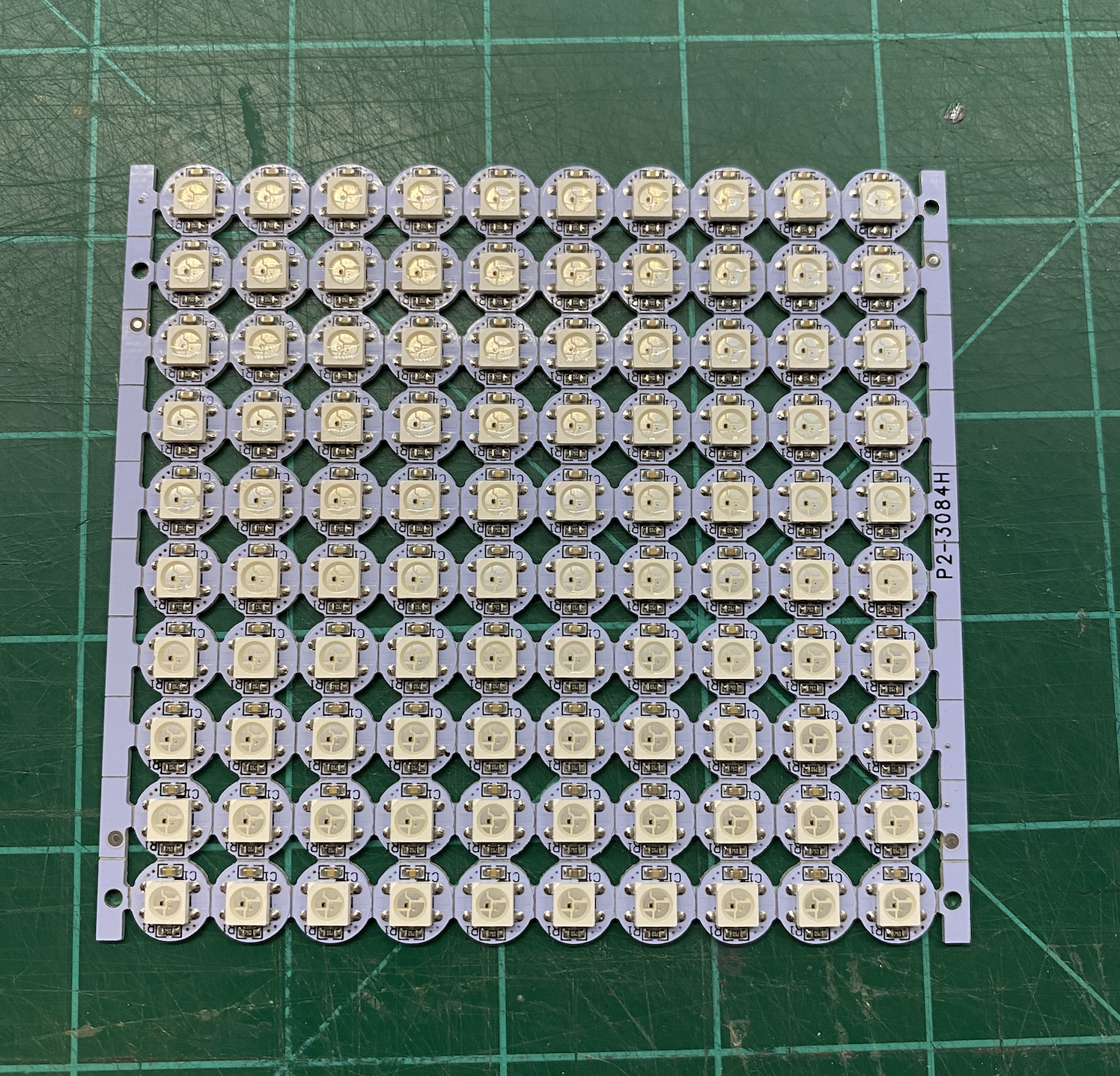
While not quite as cheap as strip LEDs, these are easy to solder and the circuit boards provide a rigid structure that can be incorporated into a 3D printed design.
The plan was to create individual panels of LEDs that could be connected to form lager panels but first I needed a prototype that incorporated a single LED, channels for wiring and support for attaching a ping pong ball. This is the initial prototype:
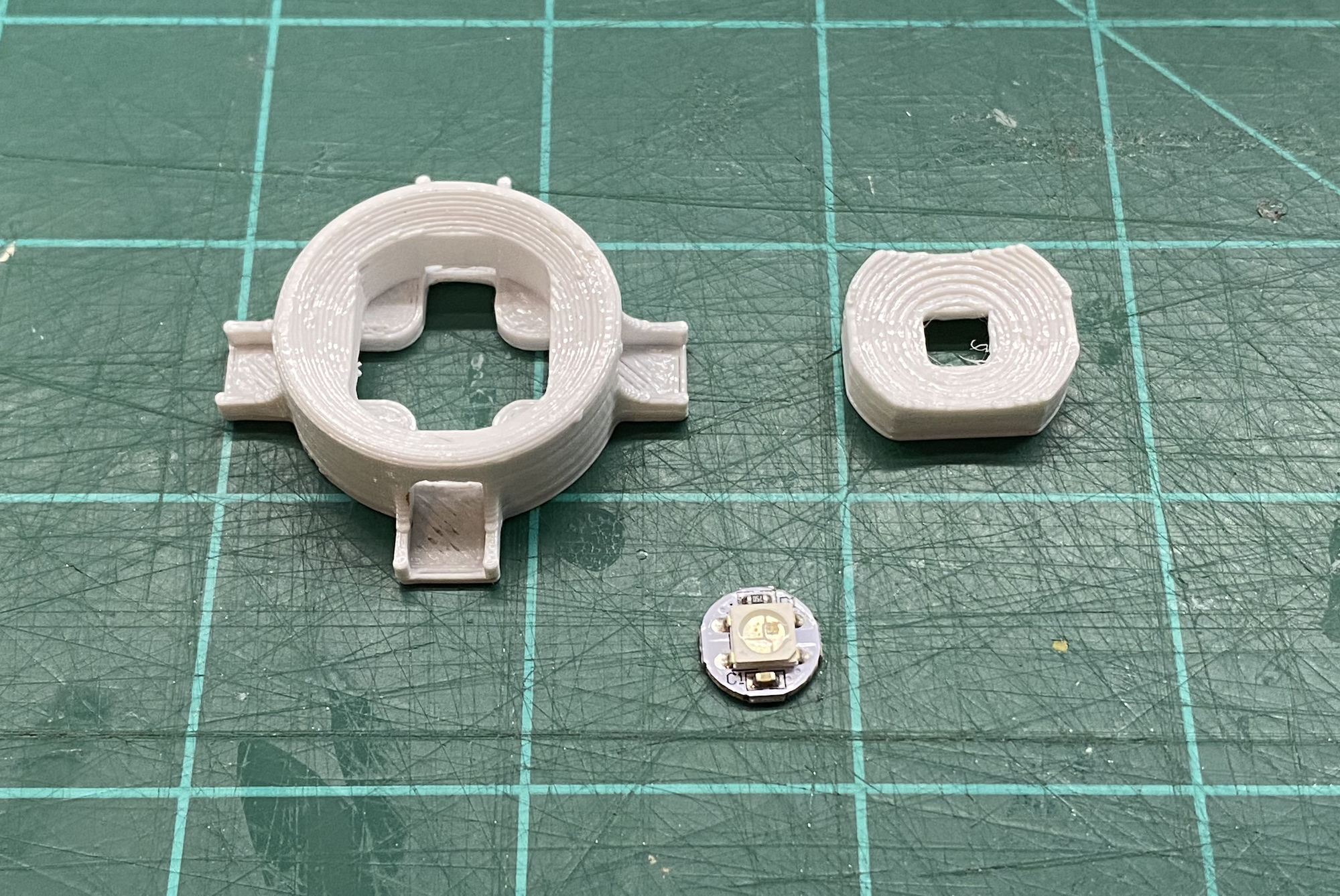
By printing the center portion of the holder separately I was able to eliminate the support material that would have been difficult to remove. It also makes the wiring very easy to access until it's time to solder in the LED. The LED insert is designed to match the circuit board and it simply press fits in place:
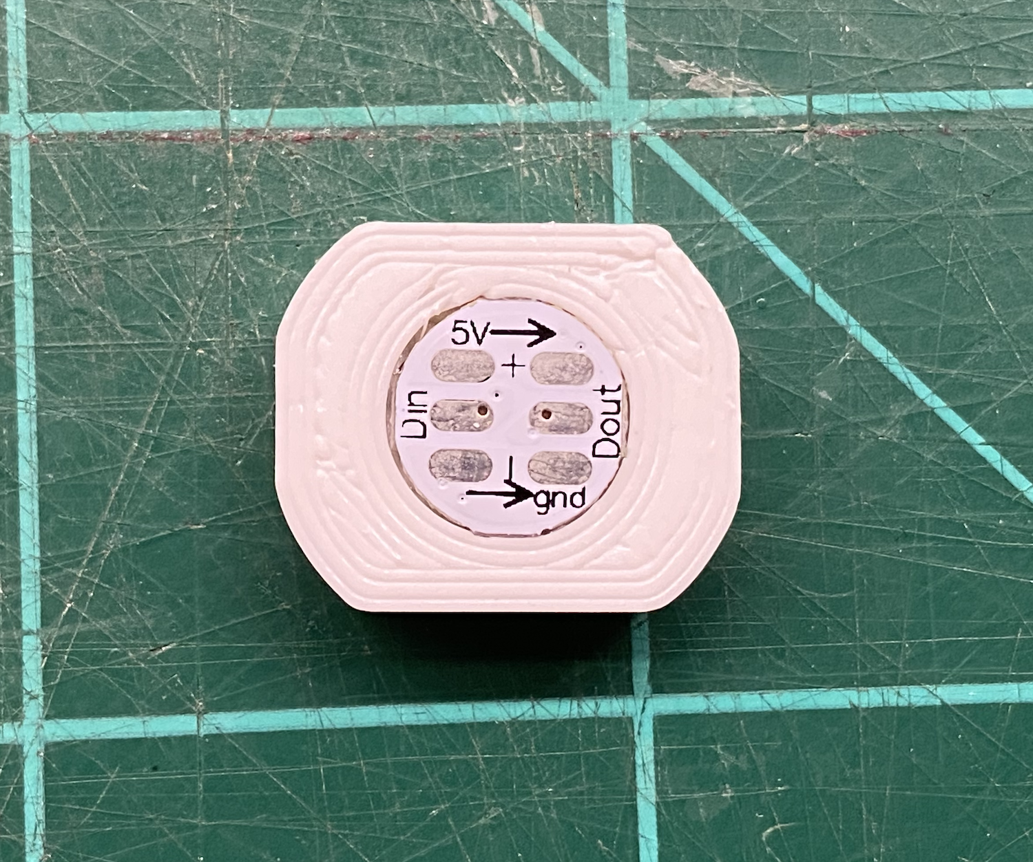
Since the insert is keyed (flat on two sides) when inserting the LED the only concern is matching the arrows to the flat sides. The insert can then be pushed into the holder as shown below:
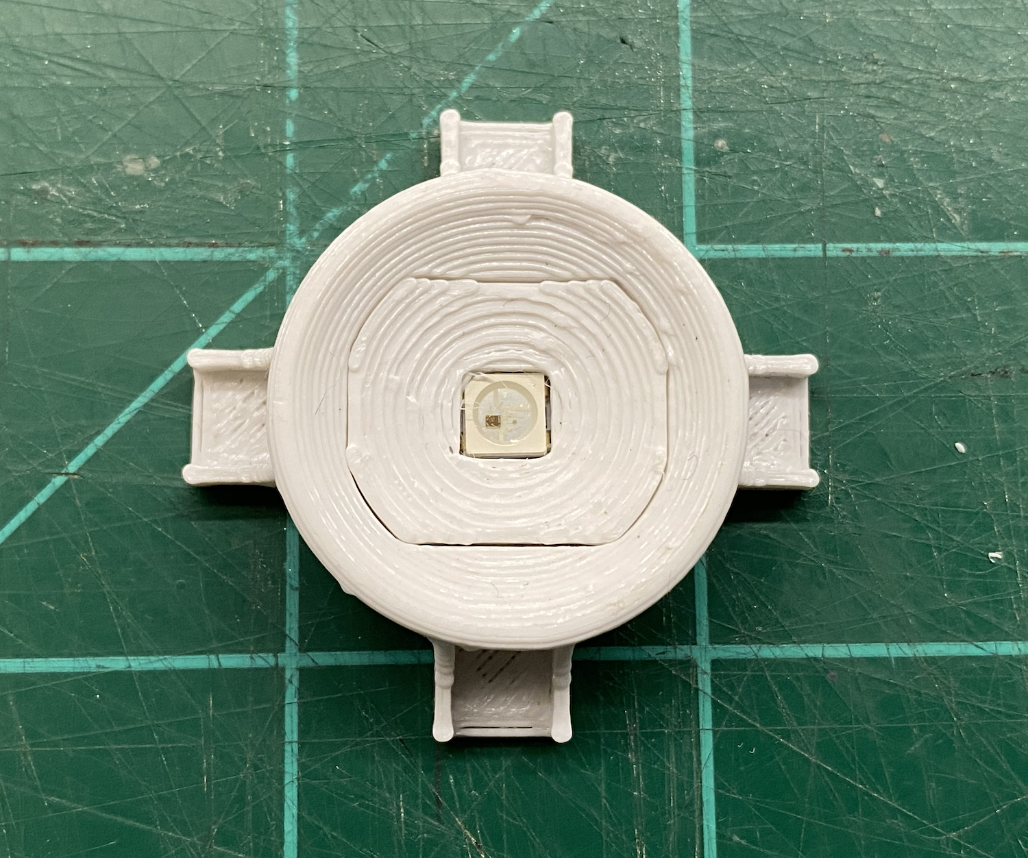
The resulting assembly forms a cup that is perfectly matched to a ping pong ball which provides a lot of surface area for attaching using a little hot glue as shown below:
With this working well, next step was to create a grid of holders. This not only needed to provide wiring channels in both X and Y directions but also provide additional cross channels in both directions for power distribution.
Anyone who has worked with large numbers of LEDs knows that power is always an issue. If you want to use multiple supplies, such as power banks, then power must be segmented. If you want to use a single large supply everything can be cross connected. Even if you use a single large supply there are still concerns about voltage drop for large arrays. To provide as much flexibility as possible the plan was to use one axis for connecting small runs of LEDs using 30awg (wire wrap wire) and then use the opposite axis to run lower gauge wire as a bus. If things grew even larger, the opposite axis distribution channel could then be used to run even lower gauge wire as distribution between the bus wires. This would keep all effective distances very short while still allowing the use of high gauge wire throughout most of the overall display.
Here is a single panel component:
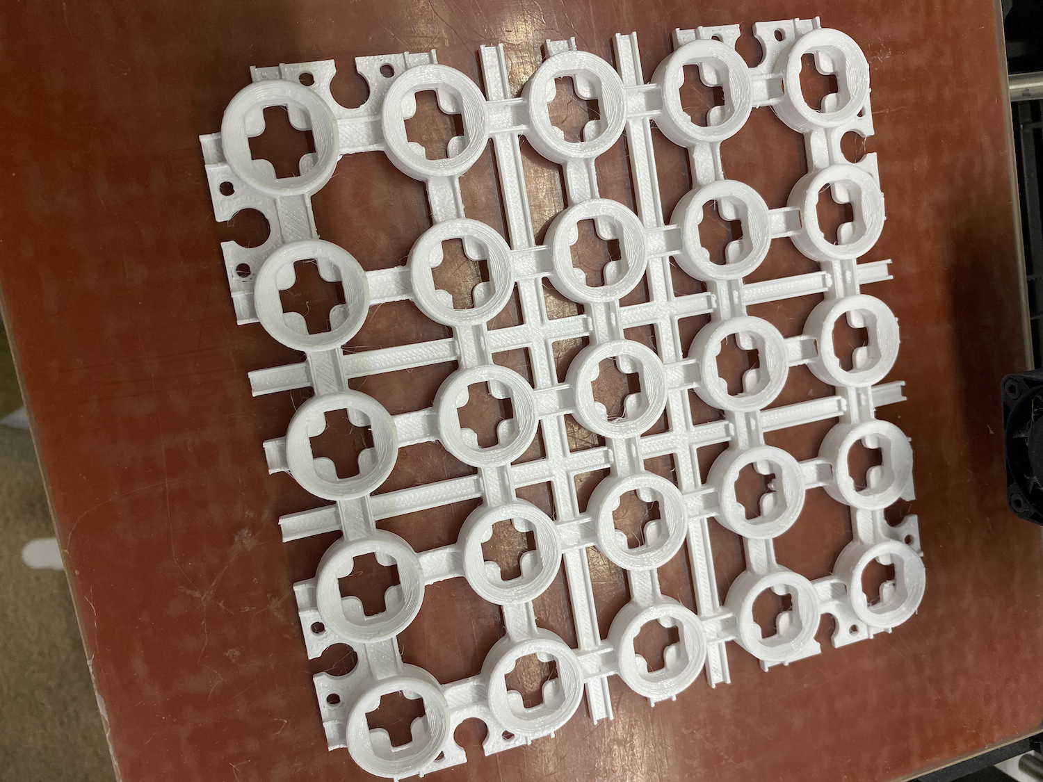
Note the pair of horizontal and vertical channels passing around the center holder. These have openings through all the various channels allowing for power distribution wiring.
Another complexity around putting together large displays is how to attach everything together. The panel above has built in screw holes around all the corners but they also contain key slots which allow multiple panels to be clipped together. The image below shows four panels combined into a larger panel using 3D printed keys in the corner slots:
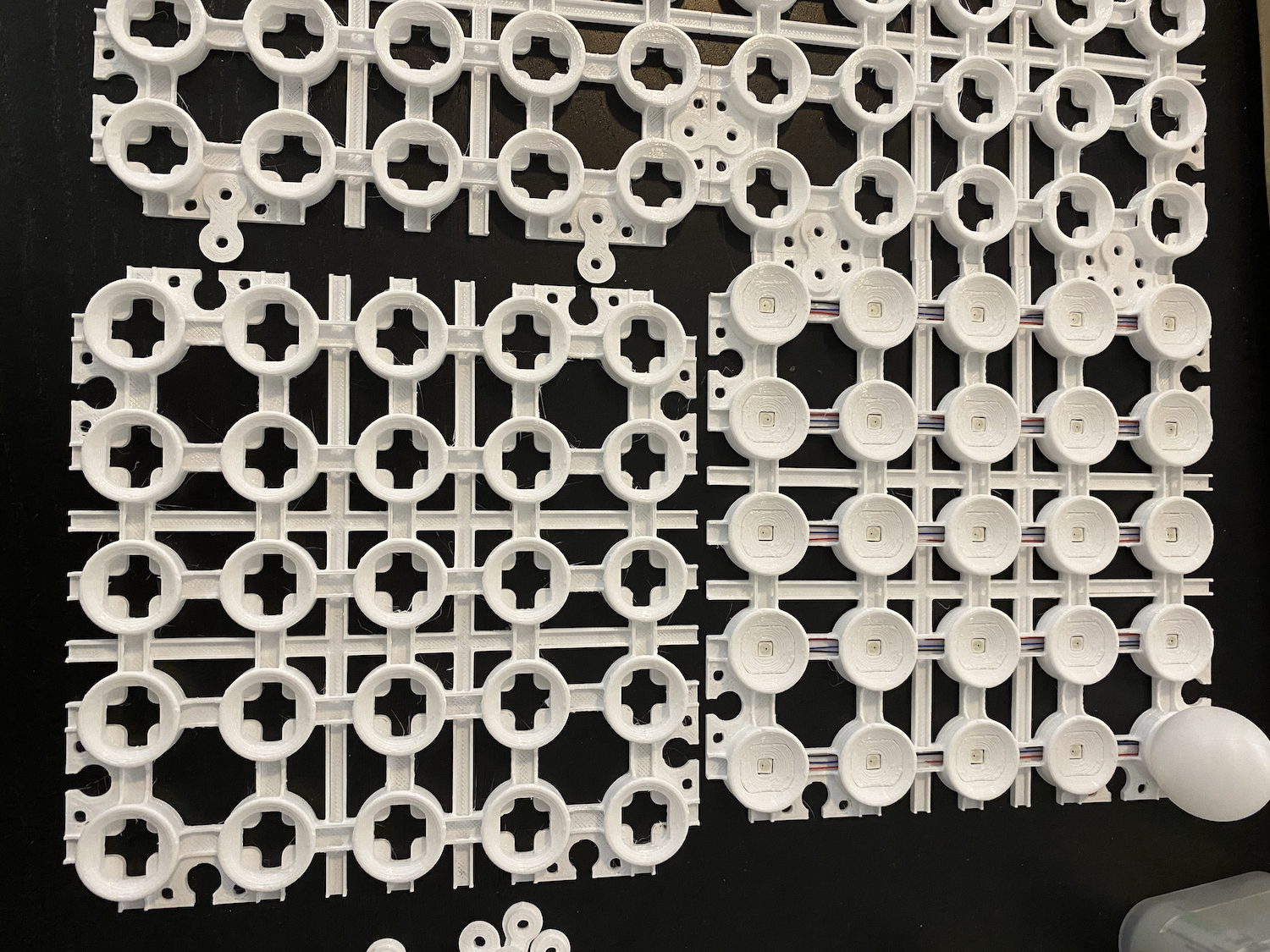
The problem with this design was that while the small clips kept things attached the overall assembly wasn't rigid. Much like a puzzle, everything stays together on a...
Read more »
 CriptasticHacker
 Koen van Vliet
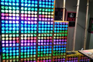
 Cadmium