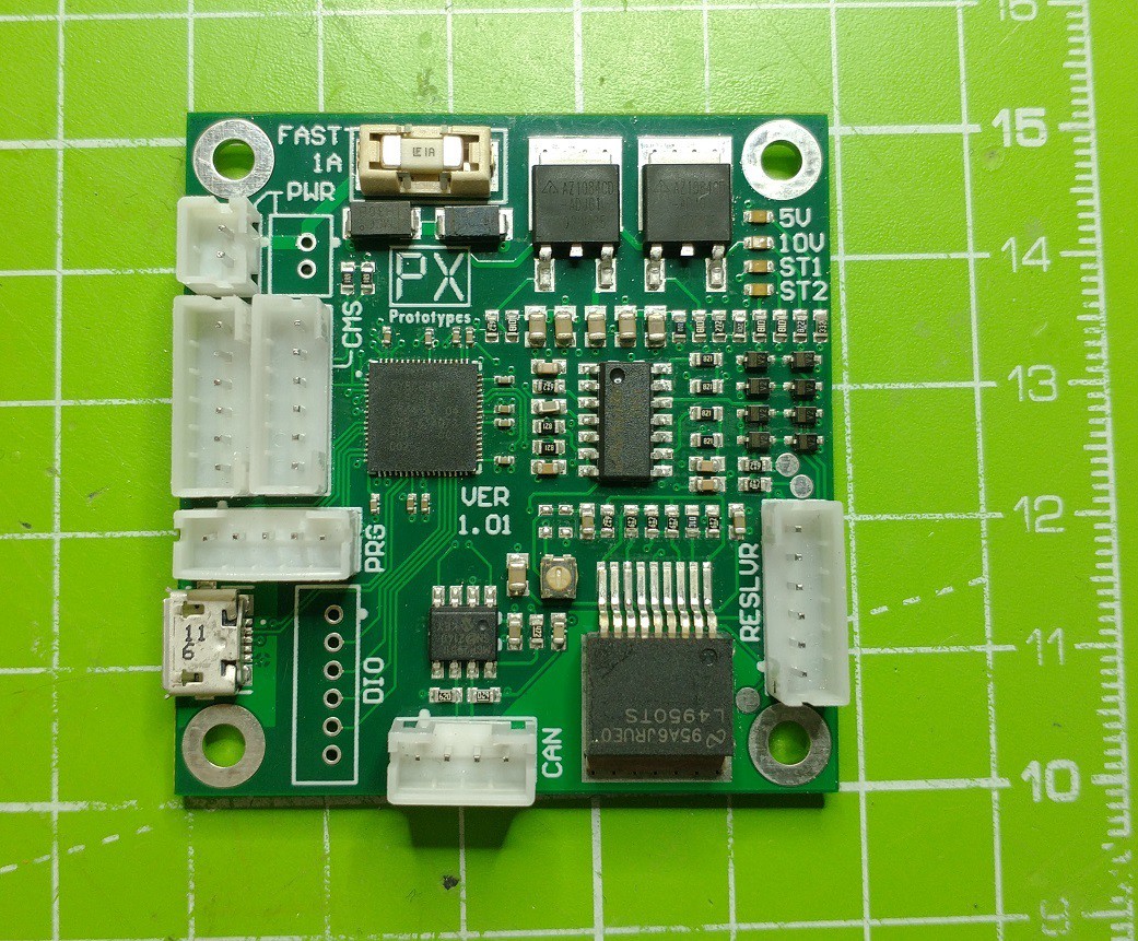
• Boards Received & Soldered

    PX Protoypes01/26/2022 at 10:32 0 comments

    The boards were received after a long delay stuck in Chinese customs

    They soldered up nicely and power up as expected

  • Theory of operation

    PX Protoypes01/03/2022 at 16:10 0 comments

    The resolver angle is read as follows:

    • A 10kHz sine wave is generated using the PSOC DAC component and filtered
    • The filtered output is fed into a LM4950TS audio amplifier IC configured as BTL to provide up to 20V pk-pk
    • A trim pot is provided to set the output voltage. Pads are provided to replace this with SM resistors once the correct values have been determined
    • The positive wave of the sin, cos and drive feedback are sampled by the PSOC at the correct time to account for any phase delay in the low pass filter and amplifier.
    • The firmware chooses which input is on the steeper part of the curve (for better accuracy) and calculates the angle quickly using a LUT.
    • The angle multiplied buy 10 is placed into the I2C emulated EEPROM buffer after every stop condition detected on the I2C bus.
    • The angle is a 15 bit unsigned int followed by an odd parity bit

    The firmware has various monitoring functions via a USB serial port as well as an automatic calibration routine to determine the resolver primary to secondary ratio for the best accuracy as well as the phase delay of the amplifier.