 Subhajit
In this Lora IoT project tutorial, I have shown how to make the LoRa Arduino ESP8266 control relay from the Blynk IoT platform with real-time feedback.

In this article, I have covered the following topics.
- Explained this ESP8266 Arduino Lora IoT-based home automation project.
- Explained Transmitter & Receiver Lora circuit.
- Setup Blynk cloud account for the ESP8266.
- Explained the source codes for this LoRA IoT project.
- Control high voltage appliances with LoRa.
Tutorial Video on the LoRa IoT Project with Blynk
So if you follow all the steps, you can easily make this Lora IoT project, to control any appliances from anywhere in the world with the combination of LoRa and Wi-Fi. So this project is very useful in rural areas where WiFi is not available.
Although the PCB is not mandatory, I have used PCB for the transmitter LoRa circuit to make the circuit compact and give the project a professional look.
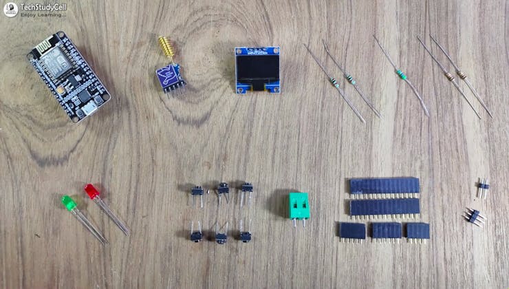
Required components for the Transmitter Lora circuit:
- Lora Module REYAX RYLR998 1no
- ESP8266 NodeMCU 1no
- 1k Resistors 2no
- 4.7k Resistor 1no
- 10k Resistor 1no
- 5-mm LED 2no
- Push-button 4no
Required components for the Receiver Arduino Lora circuit:
- Lora Module REYAX RYLR998 1no
- Arduino UNO 1no
- 5v 4-channel Relay Module 1no
- 4.7k Resistor 1no
- 10k Resistor 1no
- 5-mm LED 1no
Required Components for the PCB used for transmitter circuit:
- REYAX RYLR998 or RYLR896 Lora module 1no
- ESP8266 NodeMCU 1no
- 1k Resistors 2no
- 4.7k Resistor 1no
- 10k Resistor 2no
- 5-mm LED 2no
- Push-button 6no
- Jumper 2no
- Terminal connector 2 pin 1no
- OLED (optional)
How does this LoRa IoT Project Works?

For controlling the appliances from the smartphone, I used the Blynk IoT app.
This LoRa Wi-Fi system works in the following steps:
- When you press any button in the Blynk IoT app, the signal is sent to the Blynk Cloud.
- Through the internet, the ESP8266 NodeMCU receives the signal from the Blynk cloud.
- Afterwards, the ESP8266 sends the same signal through LoRa to Arduino.
- After receiving the signal through LoRa, Arduino turns ON/OFF related relay and sends the feedback to ESP8266 through the LoRa module.
- The ESP8266 will turn on the status LED and send the feedback to Blynk cloud once it receives feedback.
- Using the Blynk IoT app, you can also monitor real-time feedback.
Transmitter Lora Circuit Using NodeMCU ESP8266
![]()
In the transmitter LoRa circuit, I have used NodeMCU. I have made a voltage divider using 4.7k and 10k resistors to drop down the 5volt logic level to 3.3volt logic level for the LoRa module.
I have used D7 as RX and D8 as TX for the serial communication with the LoRa module.
The pushbuttons are connected with the SD3, D3, D5, and RX GPIO pins of NodeMCU.
The status LED is connected with the D4 GPIO pin.
You can use any 5V DC power supply to supply the circuit.
Receiver Lora Circuit Using Arduino UNO
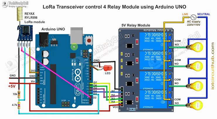
On the receiving end, I have used Arduino UNO. In the circuit, I have made a voltage divider using 4.7k and 10k resistors to drop down the 5volt logic level to 3.3volt logic level.
I have used D4, D5, D6 & D7 pins to control the 4-channel relay module.
As per the source code, when the control pins of the relay module receive the LOW signal the respective relay will turn on and the relay will turn off for the HIGH signal in the control pin.
I have used a 5V 2Amp power supply to supply the Arduino UNO and relay module.
Please take the proper safety precautions while working with high voltage.
Create New Template for ESP8266 in Blynk Cloud
For this smart house project, I have used the Blynk IoT Cloud Free plan. Click on the following link to create a Blynk Cloud account.
https://blynk.cloud/dashboard/register
Steps to Create New Template for ESP8266
- Click on New Template.
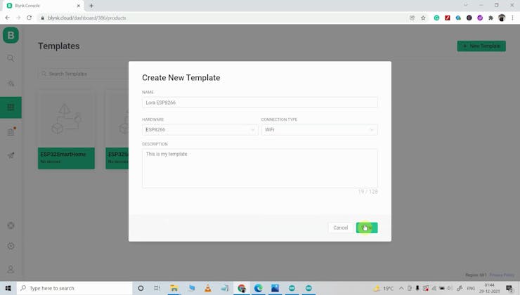
- Enter a template name, select the hardware as ESP8266, and the connection type will be WiFi.
- Then click on DONE.

You will get the BLYNK_TEMPLATE_ID and BLYNK_DEVICE_NAME after creating the temple.
Create Datastreams in Blynk Cloud
After that, you have to create Datastreams. Here I will control 4 relays, so I have to create 4 Datastreams to control 4 relays and 1 Datastream for the feedback.
Steps to Create Datastreams:
- Go to the Datastreams tab.
- Click on New Datastream and select Virtual Pin.

- Enter a name, select the virtual pinV1, and the datatype will be Integer. MIN value is "0" & MAX value is "1".
- Then click on Create.
- In a similar way, create the next datastream with virtual pin V2, V3, and V4.

- For the Feedback create the last Datastram with virtual pin V5, and datatype will be String.
- Then click on Create.

- Then click on "Save".
Add Device Using Template in Blynk IoT
Steps to add a device in Blynk IoT cloud:

- First, go to Device, then click on "New Device".

- Click on "From template".

- Select the Template, and give the device name.
- Click on Create.

Then in the device info tab, you will get the Blynk Auth Token, Template ID, and Device Name. All these details will be required in the code.
PCB Used for the Transmitter LoRa Circuit
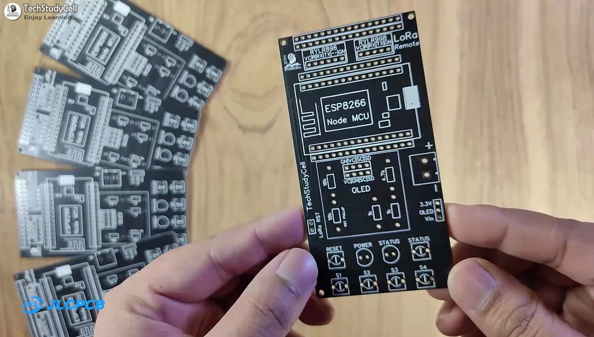
To make the circuit compact and give a professional look, I have designed the PCB for the transmitter end LoRa circuit.
You can download the PCB Gerber file of this Lora project from the following link:
GitHub to Download PCB Gerber File
Order the PCB from JLCPCB
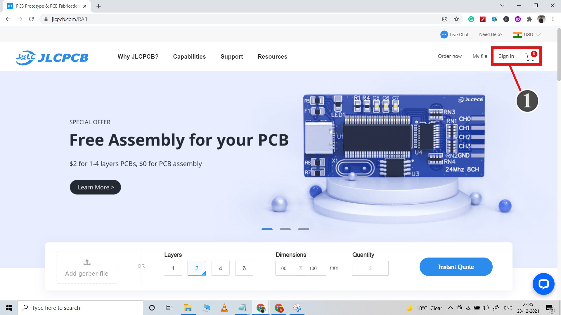
After downloading the Garber file you can easily order the PCB
1. Visit https://jlcpcb.comand Sign in / Sign up.

2. Click on the QUOTE NOW button.

3. Click on the "Add your Gerber file" button. Then browse and select the Gerber file you have downloaded.
Uploading the Gerber File and Set the Parameters

4. Set the required parameter like Quantity, PCB masking color, etc.

5. After selecting all the Parameters for PCB click on SAVE TO CART button.
Select Shipping Address and Payment Mode

6. Type the Shipping Address.
7. Select the Shipping Method suitable for you.
8. Submit the order and proceed with the payment.
You can also track your order from the JLCPCB

My PCBs took 2 days to get manufactured and arrived within a week using the DHL delivery option.
PCBs were well packed and the quality was really good at this affordable price.
Solder All the Components on PCB

After that, I have soldered all the components as per the circuit diagram.
Then connect the NodeMCU board and Lora module with the PCB.
Codes for This LoRa Project Using Arduino and ESP8266

In this Lora Project, I have used NodeMCU for the transmitter circuit, and Arduino UNO for the receiving circuit.
First, download the source codes. GitHub Download link.

In the TX code for NodeMCU, enter the Blynk Auth Token, Template ID, and Device Name
#define BLYNK_TEMPLATE_ID ""
#define BLYNK_DEVICE_NAME ""
#define BLYNK_AUTH_TOKEN ""
Then enter the WiFi Name and Password.
char ssid[] = "";
char pass[] = "";
Then upload the code for the transmitter circuit to NodeMCU.
After that upload the code of the receiving circuit to Arduino UNO.
*** You do not have to configure the Lora modules separately for this project. During the boot process of the microcontroller, the void setup() function will execute all AT commands that are required.
*** Here I have used the 865MHz band. Please enter the BAND in the code as per the eligible LoRa band in your country.
*** Do not disconnect Lora modules from the microcontrollers, and after programming wait till the status LED in both circuits turn OFF.
Set Up Blynk IoT App Mobile Dashboard
Install the Blynk IoT app from Google Play Store or App Store. Then log in and Tap on Developer Mode. Select the template that you have already made Then go to the Widget box (on the right) to add widgets.
Steps to set up Blynk IoT app Mobile Dashboard
- Add 4 Button widgets and 1 Value DIsplay widget from Widget Box.
- Go to Button widget settings.
- Enter the name, select Datastream, Mode will be PUSH.
- For the Value DIsplay widget select Datastream, and Front size.
- After configuring all the widgets tap on exit.
If the NodeMCU is connected with WiFi the BLUE LED (D0 GPIO) will turn ON.
Please watch the complete tutorial video for more details. (shared in step 1)
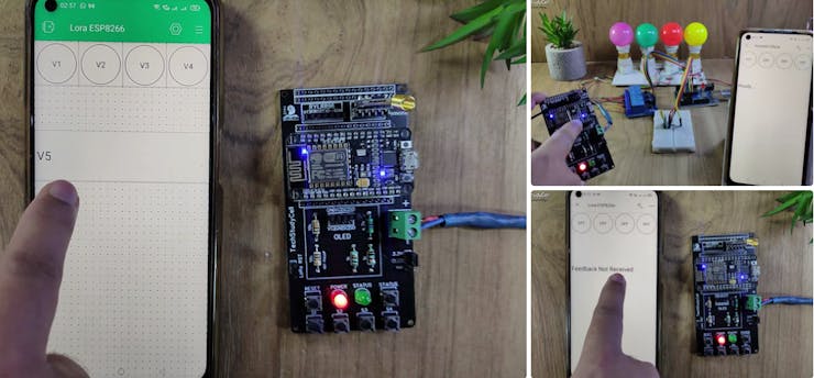
Control the Appliances With Blynk IoT (Lora WiFi)

If the NodeMCU is connected with WiFi, then you can control the relays and monitor feedback from Blynk IoT App.
You also use multiple smartphones to control the appliances with Blynk IoT App. For that, you have to log in same Blynk account from all the smartphones. In this way, all smartphones will be sink to the Blynk server.
Control Relays From Pushbutton Through Lora

You can also control the appliances with the transmitter LoRa circuit using pushbuttons and also monitor the real-time feedback from the receiver LoRa circuit.
After receiving the feedback the status LED will turn ON.
Please make sure there should not be any loose connection, otherwise, this circuit may not work.
In the future, I will try to add more features to this LoRa project.
I will really appreciate it if you share your valuable feedbacks. Also if you have any query please write in the comment section.
Thank you & Happy Learning.