 Steven J Greenfield
I have used the same basic circuit for all kinds of capacitive sensing. Touch switches, presence sensor, level sensing for liquids from water, to ink, to gasoline and oil.
I built a multiple capacitive sensor that compared capacitance to operate a servo. I was commissioned to do this for a Halloween skull that would rotate to face anyone approaching.
I designed circuits to allow remote sensing with 2 wires, and a circuit that uses a driven shield to shield a large sensor from parasitic capacitance that would otherwise desensitize it. About 20 years later, someone at NASA thought of the same thing and patented it.
The operation of the circuit is fairly simple. Please note that, although I used a TLC556, which is a dual 555 timer in the circuit, on the schematic the pin numbers assume two separate TLC555 timers.
The first section of the timer, wired as an astable oscillator, provides a steady clock signal with a very short Off pulse, which goes to the Trigger input of the second section of the timer.
The second section of the timer is wired as a monostable. The On time is determined by the resistor selected and the unknown capacitance connected to pins 6 and 7.
The output is therefore a PWM signal with constant clock speed, and the PWM percentage is a linear function of the capacitance being measured.
An RC lowpass filters this PWM to a low ripple DC signal. A ten turn trimpot is used as the Calibration adjustment and goes to the red positive lead of your DMM.
The black negative lead of the DMM goes to a voltage divider which compensates for the PWM output caused by parasitic capacitance. This is done as a front panel control for zeroing, so you can attach test leads and zero them out before connecting a capacitor.
C1 is a mylar capacitor, aka polyester film, as it was a reasonably priced temperature stable capacitor in that range of capacitance.
The low pass capacitor at the output is not critical in value or type. I just used a 4.7uF aluminum electrolytic capacitor.
 jaromir.sukuba
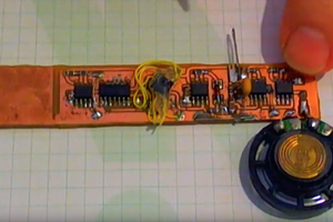
 matseng
 Ted Yapo
 Yann Guidon / YGDES